Fluke Biomedical 956A-201-M2 User Manual
Page 65
3-39
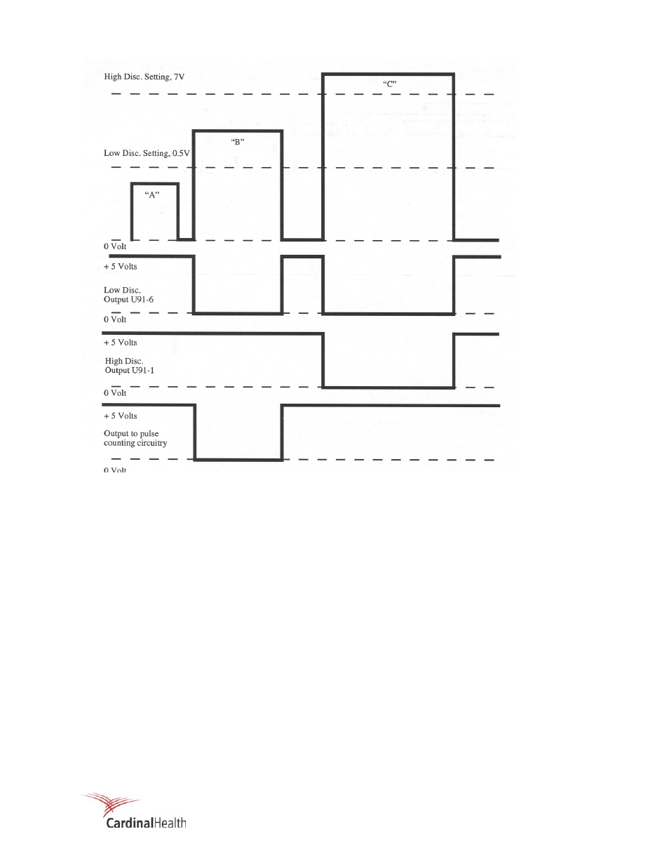
Figure 3-6. Discriminator Operation
a. This pulse is below the low discriminator voltage and is not passed.
b. This pulse is above the low discriminator voltage and below the upper discriminator voltage, and is
passed to the counters.
c. This pulse is above the upper discriminator and is not passed.
Signal Detection
The circuitry comprised of flip-flop U93 and inverters U11 and U94 utilize the low discriminator and high
discriminator outputs to ensure that only input signals which peak between the discriminators are made
available to the gross counters.
When U93A-2 counter enable is brought high, under software control (COUNTER ENABLE) to initiate a
sample period, and the low discriminator threshold is exceeded, a positive going edge on U93A-3 clocks a
high from flip-flop U93A-5. Assuming the high discriminator has not been exceeded, when the input pulse
returns through the low discriminator threshold, a positive going edge on U93B-11 clocks the high on
U93B-12 to the output U93B-9. A delayed positive pulse produced by the R/C network (R80/C35) on
U93B-13 allows the flip-flop output U93B-9 to remain high until the delayed pulse on U93B-13 returns low,
which resets the output U93B-9 low. U93B-9 is connected to the signal multiplexer circuitry as described
below.