Fluke Biomedical 956A-201-M2 User Manual
Page 56
3-30
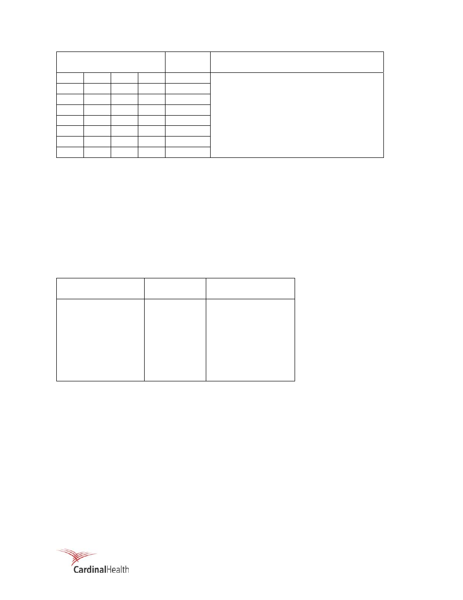
Table 3-7. U1 Outputs
ADDRESS STATE
A8 A7 A6 A5
ADDRESS FUNCTION
0 0 0 0
4000 Register
Select
(/REGSELECT)
0 0 0 1
4020 Bargraph
(/BARGRAPH)
0
0
1
0
4040
ACIA (/ACIA, Communication Interface, optional)
0
0
1
1
4060
SCA (/SCA, Analyzer, optional)
0 1 0 0
4080 GPIB
(/GPIB,
General Purpose Interface Bus)
0 1 0 1
40A0 Analog
Input
Option
(/AIO)
0 1 1 0
40C0 (Spare
1)
0 1 1 1
40E0 (Spare
2)
Address 4000 is further decoded by the write register decoder (U2) and the read register decoder (U34).
The bargraph output, address 4020, is further decoded by U5 (Table 3-11). The remaining output
addresses (4040 through 40E0) are provided to the optional interface connector for use by external option
circuit boards.
Read Register Decoding
Decoding for READ registers within the main circuit board is performed by U34, which is a 1 of 8 decoder.
Control signals for U34 are REG SELECT, and R/W (Read/Write) (active high) as well as address A1, A2,
and A3. U34 decodes address per output, starting with 4000 and ending with 400E. These outputs are
active low. Table 3-8 lists the READ register, the assigned function and the address.
Table 3-8. Control Signal Address Decoding (U34)
Address State
A3 A2 A1
Hex Address
Function
0 0 0
4000
Switch
Interface
0 0 1
4002
Data
Entry
0
1
0
4004
Gross Counter Low
0
1
1
4006
Gross Counter High
1 0 0
4008
Sensitivity
Select
1 0 1
400A
(Spare)
1 1 0
400C
(Spare)
1 1 1
400E
(Spare)
Data Entry (Read Only)
Octal buffer U36 functions as an interface to supply the status of the switches for data entry to the internal
data bus address (4002) and storage in the EE PROM U33. The data entry read functions are shown in
Table 3-9. The function switch logic is shown in Table 3-10.