NavCom SR-7120 Rev.A User Manual
Page 54
Safari Network User Guide
2. Connect the J1 cable into the J1 connector, and the J2
cable into the J2 connector. The connectors are keyed
to only fit one way.
J1 cable
J2 cable
Figure 3-7: Use of J1 Cable
3. Connect the four 20 AWG wires at the other end of
the J1 cable as follows:
• Connect the red wire to the Vdc + of the voltage
source.
• Connect the green wire to the Ground of the
voltage source.
• Connect the white wire to the ignition signal. If
there is no ignition signal, connect the white wire
to the red wire at the voltage source.
• Connect the black wire to the chassis ground.
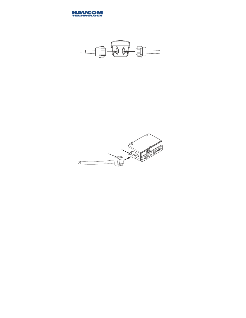
4. Connect the other end of the J2 cable to the end of
the Port Expander.
Figure 3-8: J2 to Port Expander Connection
Black
connector
Black
key
5. Turn on the Port Expander. This will turn on the
radio.
3-8