Configuring the network – NavCom SR-7120 Rev.A User Manual
Page 67
Advertising
Safari Network User Guide
Press x to return to the Admin Page. Press 5 plus enter,
followed within 10 seconds with “admin”.
Configuring the network
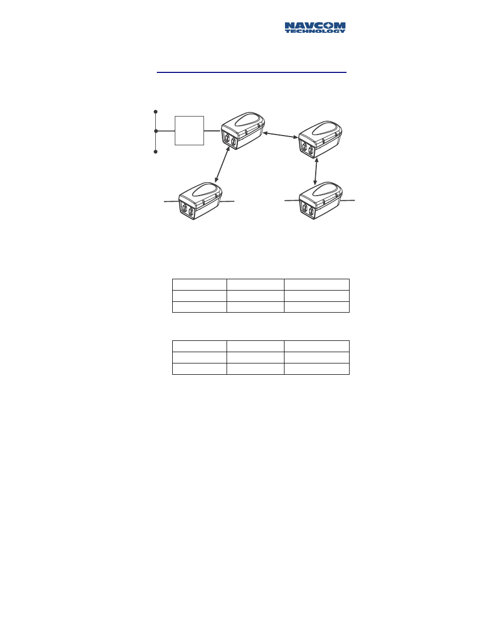
To illustrate the logic of network configuration, let’s
consider an example of a typical network system.
NCU
ID = 301
SC
Router
ID = 100
ID = 302
RU
RU
ID = 201
ID = 202
Figure 4-2: Sample Network
There is 1 NCU with a physical ID of 6F3A6E8. It will
be automatically assigned Unit ID 100.
There are 2 RUs:
RU
Physical ID
Assigned Unit ID
1 6F3FFFF
201
2 6F3EEEE
202
There is 1 SCU containing two radio modules named
SCU uplink and SCU downlink.
SCU
Physical ID
Assigned Unit ID
SCU uplink
6F3DDDD
301
SCU downlink
6F3CCCC
302
4-5
Advertising