Network interface pin assignments, Supervisory and auxiliary port pin assignments – Verilink WANsuite 5370 (34-00310.D) Product Manual User Manual
Page 224
Advertising
A-8
W A N s u i t e 5 3 7 0
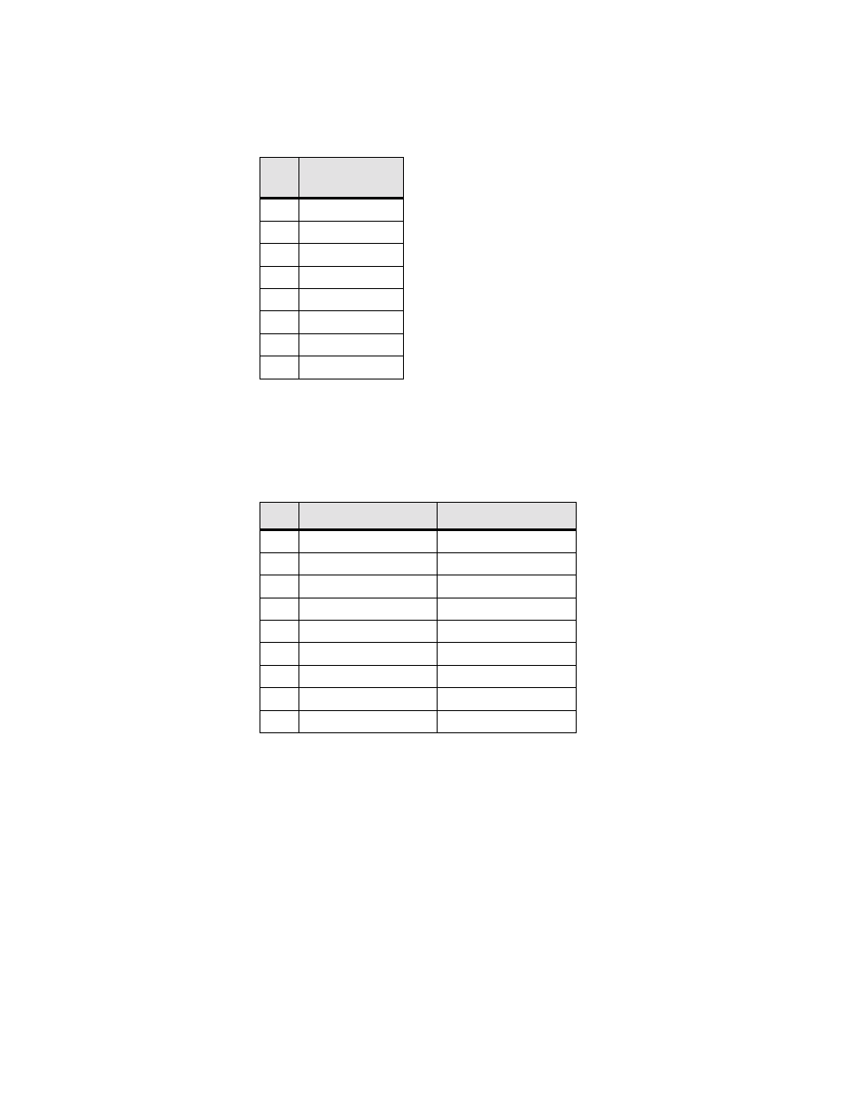
Network Interface Pin Assignments
The
NET
physical interface is a standard RJ-48C, 8 -pin modular jack. The
table below displays the pinout assignments.
Supervisory and Auxiliary Port Pin Assignments
Both the
SUPERVISORY and AUXILIARY PORT
interfaces are standard DB-9,
9- pin modular jacks. The table below displays the pinout assignments for
both these ports.
Pin
DDS Network
Interface
1
Data Out
2
Data Out
3
Not used
4
Not used
5
Not used
6
Not used
7
Data In
8
Data In
Pin
DCE Mode
DTE Mode
1
DCD out
LL out
2
Rx Data out
Tx Data out
3
Tx Data in
Rx Data in
4
DTR in
DSR in
5
Signal Ground
Signal Ground
6
DSR out
DTR out
7
RTS in
CTS in
8
CTS out
RTS out
9
No connect
No connect
Advertising
This manual is related to the following products: