Is-is nsr configuration example, Network requirements, Configuration procedure – H3C Technologies H3C S12500 Series Switches User Manual
Page 197
181
T2 Timer Status:
Remaining Time: 59
IS-IS(1) Level-2 Restart Status
Restart Interval: 150
SA Bit Supported
Total Number of Interfaces = 1
Restart Status: RESTARTING
Number of LSPs Awaited: 3
T3 Timer Status:
Remaining Time: 140
T2 Timer Status:
Remaining Time: 59
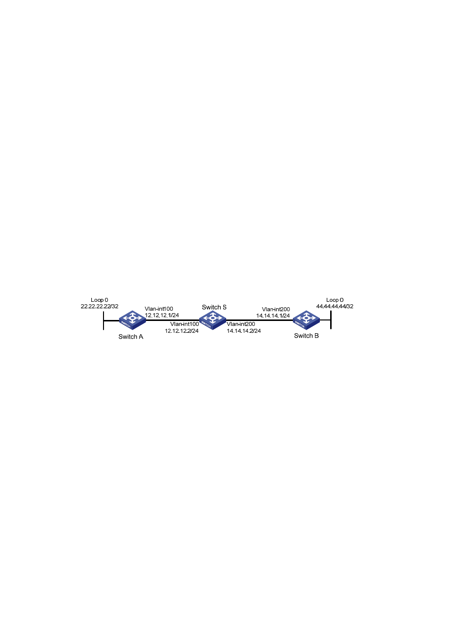
IS-IS NSR configuration example
Network requirements
Switch S, Switch A, and Switch B belong to the same IS-IS routing domain as illustrated in
Enable IS-IS NSR on Switch S to ensure correct routing when an active/standby switchover occurs on
Switch S.
Figure 69 Network diagram
Configuration procedure
1.
Configure IP addresses and subnet masks for interfaces on the switches. (Details not shown.)
2.
Configure IS-IS on the switches to make sure that Switch S, Switch A, and Switch B can
communicate with each other at Layer 3, and dynamic route update can be implemented among
them with IS-IS. (Details not shown.)
3.
Enable IS-IS NSR on Switch S.
<SwitchS> system-view
[SwitchS] isis 1
[SwitchS-isis-1] non-stop-routing
[SwitchS-isis-1] non-stop-routing interval 30
[SwitchS-isis-1] return
4.
Verify the configuration:
After Switch S establishes neighbor relationships with Switch A and Switch B, they start to
exchange routing information. After network convergence, perform an active/standby switchover
on Switch S. During the switchover period, use the display isis peer command to check the
neighbor relationship between Switch A and Switch S and between Switch B and Switch S; use the
display isis route command to check if there are routes from Switch A to the loopback interface on
Switch B and from Switch B to the loopback interface on Switch A.
# Perform an active/standby switchover on Switch S.