Configuration procedure – H3C Technologies H3C S12500 Series Switches User Manual
Page 349
333
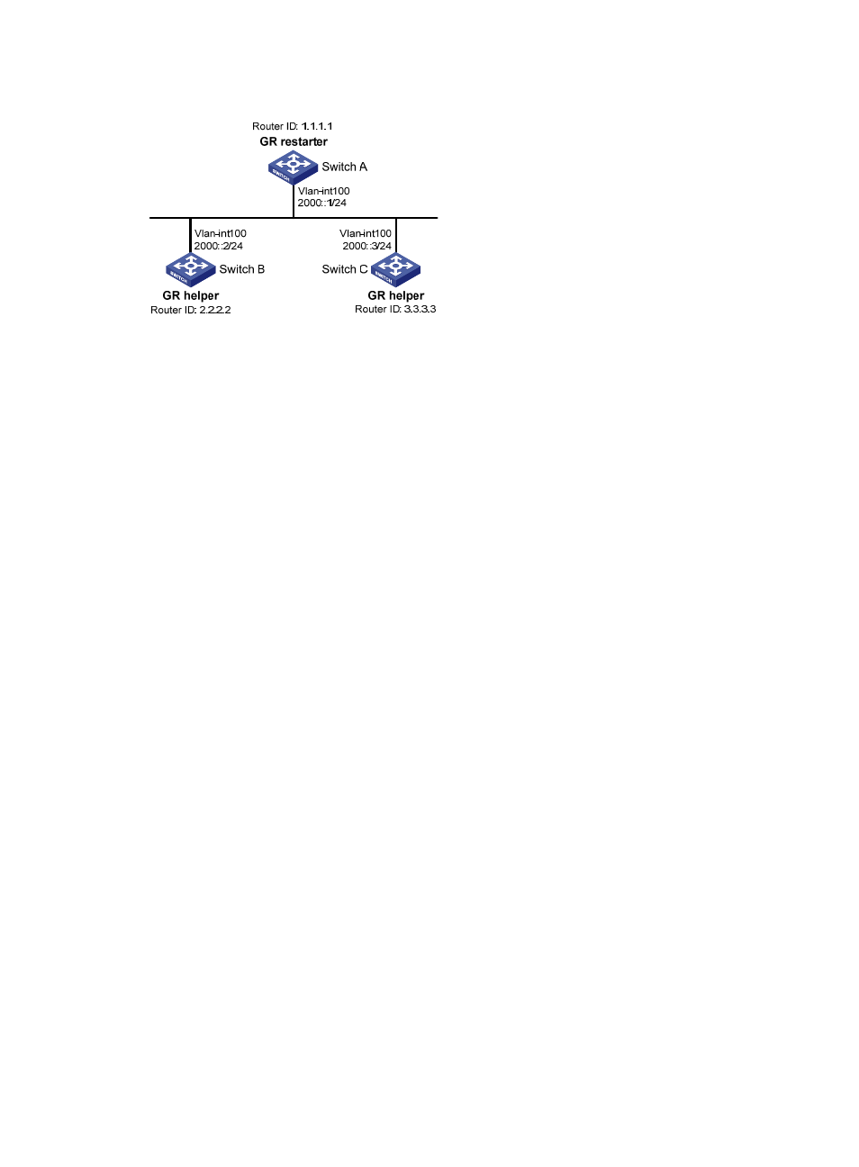
Figure 111 Network diagram
Configuration procedure
1.
Configure IPv6 addresses for interfaces. (Details not shown.)
2.
Configure basic OSPFv3:
# On Switch A, enable OSPFv3 process 1, enable GR, and set the router ID to 1.1.1.1.
<SwitchA> system-view
[SwitchA] ipv6
[SwitchA] ospfv3 1
[SwitchA-ospfv3-1] router-id 1.1.1.1
[SwitchA-ospfv3-1] graceful-restart enable
[SwitchA-ospfv3-1] quit
[SwitchA] interface vlan-interface 100
[SwitchA-Vlan-interface100] ospfv3 1 area 1
[SwitchA-Vlan-interface100] quit
# Enable OSPFv3 on Switch B and set the router ID to 2.2.2.2. (By default, GR helper is enabled
on Switch B.)
<SwitchB> system-view
[SwitchB] ipv6
[SwitchB] ospfv3 1
[SwitchB-ospfv3-1] router-id 2.2.2.2
[SwitchB-ospfv3-1] quit
[SwitchB] interface vlan-interface 100
[SwitchB-Vlan-interface100] ospfv3 1 area 1
[SwitchB-Vlan-interface100] quit
# Enable OSPFv3 on Switch C and set the router ID to 3.3.3.3. (By default, GR helper is enabled
on Switch C.)
<SwitchC> system-view
[SwitchC] ipv6
[SwitchC] ospfv3 1
[SwitchC-ospfv3-1] router-id 3.3.3.3
[SwitchC-ospfv3-1] quit
[SwitchC] interface vlan-interface 100
[SwitchC-Vlan-interface100] ospfv3 1 area 1
[SwitchC-Vlan-interface100] quit
3.
Verify the configuration: