Is-is frr configuration example, Network requirements, Configuration procedure – H3C Technologies H3C S12500 Series Switches User Manual
Page 199
183
Route information for ISIS(1)
-----------------------------
ISIS(1) IPv4 Level-1 Forwarding Table
-------------------------------------
IPV4 Destination IntCost ExtCost ExitInterface NextHop Flags
--------------------------------------------------------------------------
14.14.14.0/24 10 NULL vlan200 Direct D/L/-
44.44.44.44/32 10 NULL Loop0 Direct D/-/-
12.12.12.0/32 10 NULL vlan200 14.14.14.4 R/L/-
22.22.22.22/32 10 NULL vlan200 14.14.14.4 R/L/-
Flags: D-Direct, R-Added to RM, L-Advertised in LSPs, U-Up/Down Bit Set
ISIS(1) IPv4 Level-2 Forwarding Table
-------------------------------------
IPV4 Destination IntCost ExtCost ExitInterface NextHop Flags
--------------------------------------------------------------------------
14.14.14.0/24 10 NULL vlan200 Direct D/L/-
44.44.44.44/32 10 NULL Loop0 Direct D/-/-
12.12.12.0/32 10 NULL
22.22.22.22/32 10 NULL
Flags: D-Direct, R-Added to RM, L-Advertised in LSPs, U-Up/Down Bit Set
The output shows that the neighbor relationships and routing information on Switch A and Switch
B have not changed, which means the neighbors cannot sense the switchover on Switch S.
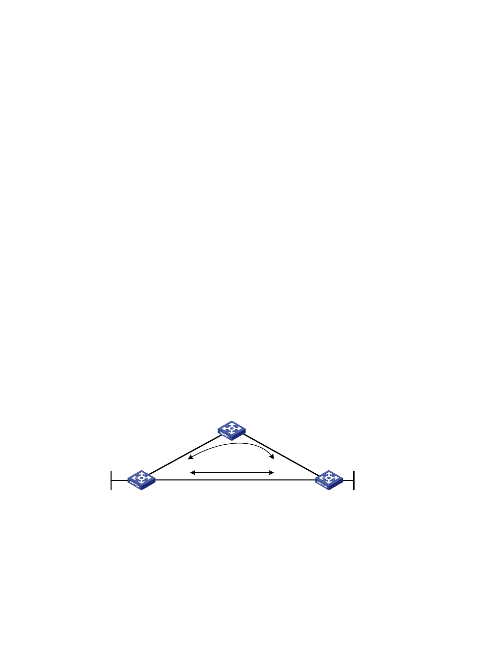
IS-IS FRR configuration example
Network requirements
Switch S, Switch A, and Switch D belong to the same IS-IS routing domain, as illustrated in
.
Configure IS-IS FRR so that when Link A between Switch S and Switch D fails, traffic is switched to Link B
immediately.
Figure 70 Network diagram
Configuration procedure
1.
Configure IP addresses and subnet masks for interface on the switches. (Details not shown.)
2.
Configure IS-IS on the switches to make sure that Switch A, Switch D, and Switch S can
communicate with each other at Layer 3, and dynamic route update can be implemented among
them with IS-IS.
3.
Configure IS-IS FRR:
Switch S
Switch D
Switch A
Loop 0
1.1.1.1/32
Vla
n-i
nt1
00
12
.12
.12
.1/
24
Vlan-int200
13.13.13.1/24
Vlan-int200
13.13.13.2/24
Vla
n-i
nt1
00
12
.12
.12
.2/
24
Vla
n-in
t10
1
24.2
4.2
4.2
/24
Vla
n-in
t10
1
24.2
4.2
4.4
/24
Loop 0
4.4.4.4/32
Link A
Link B