Configuration procedure – H3C Technologies H3C S12500 Series Switches User Manual
Page 293
277
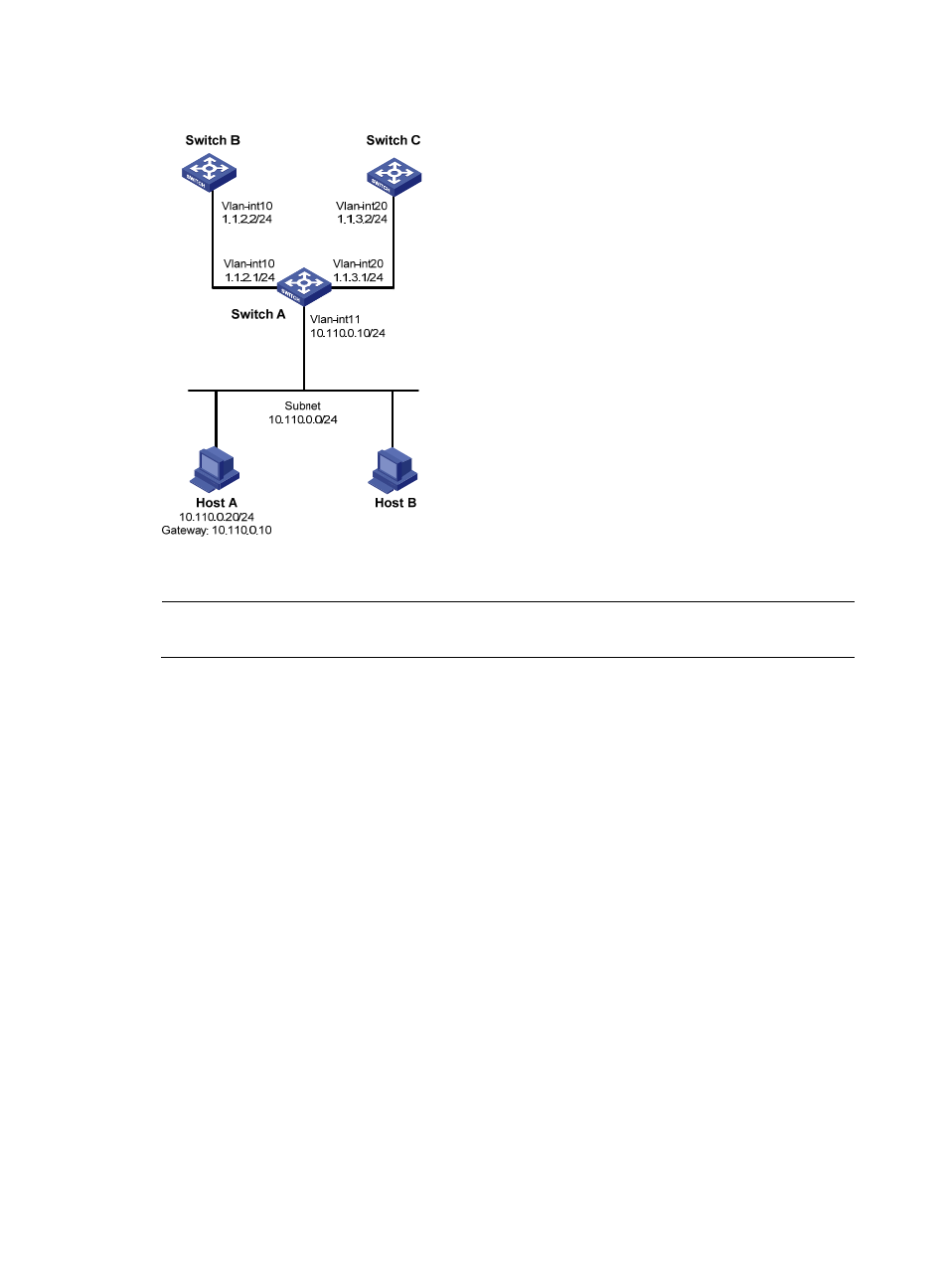
Figure 97 Network diagram
Configuration procedure
NOTE:
In this example, static routes are configured to ensure the reachability among switches.
1.
Configure Switch A:
# Define ACL 3101 to match TCP packets.
<SwitchA> system-view
[SwitchA] acl number 3101
[SwitchA-acl-adv-3101] rule permit tcp
[SwitchA-acl-adv-3101] quit
# Define Node 5 of policy aaa, which forwards TCP packets to next hop 1.1.2.2.
[SwitchA] policy-based-route aaa permit node 5
[SwitchA-pbr-aaa-5] if-match acl 3101
[SwitchA-pbr-aaa-5] apply ip-address next-hop 1.1.2.2
[SwitchA-pbr-aaa-5] quit
# Apply the policy aaa to VLAN-interface 11.
[SwitchA] interface vlan-interface 11
[SwitchA-Vlan-interface11] ip address 10.110.0.10 255.255.255.0
[SwitchA-Vlan-interface11] ip policy-based-route aaa
[SwitchA-Vlan-interface11] quit
# Configure the IP addresses of VLAN-interface 10 and VLAN-interface 20.
[SwitchA] interface vlan-interface 10
[SwitchA-Vlan-interface10] ip address 1.1.2.1 255.255.255.0
[SwitchA-Vlan-interface10] quit
[SwitchA] interface vlan-interface 20
[SwitchA-Vlan-interface20] ip address 1.1.3.1 255.255.255.0