Bgp and igp synchronization configuration, Network requirements, Configuration procedure – H3C Technologies H3C S12500 Series Switches User Manual
Page 264
248
BGP and IGP synchronization configuration
Network requirements
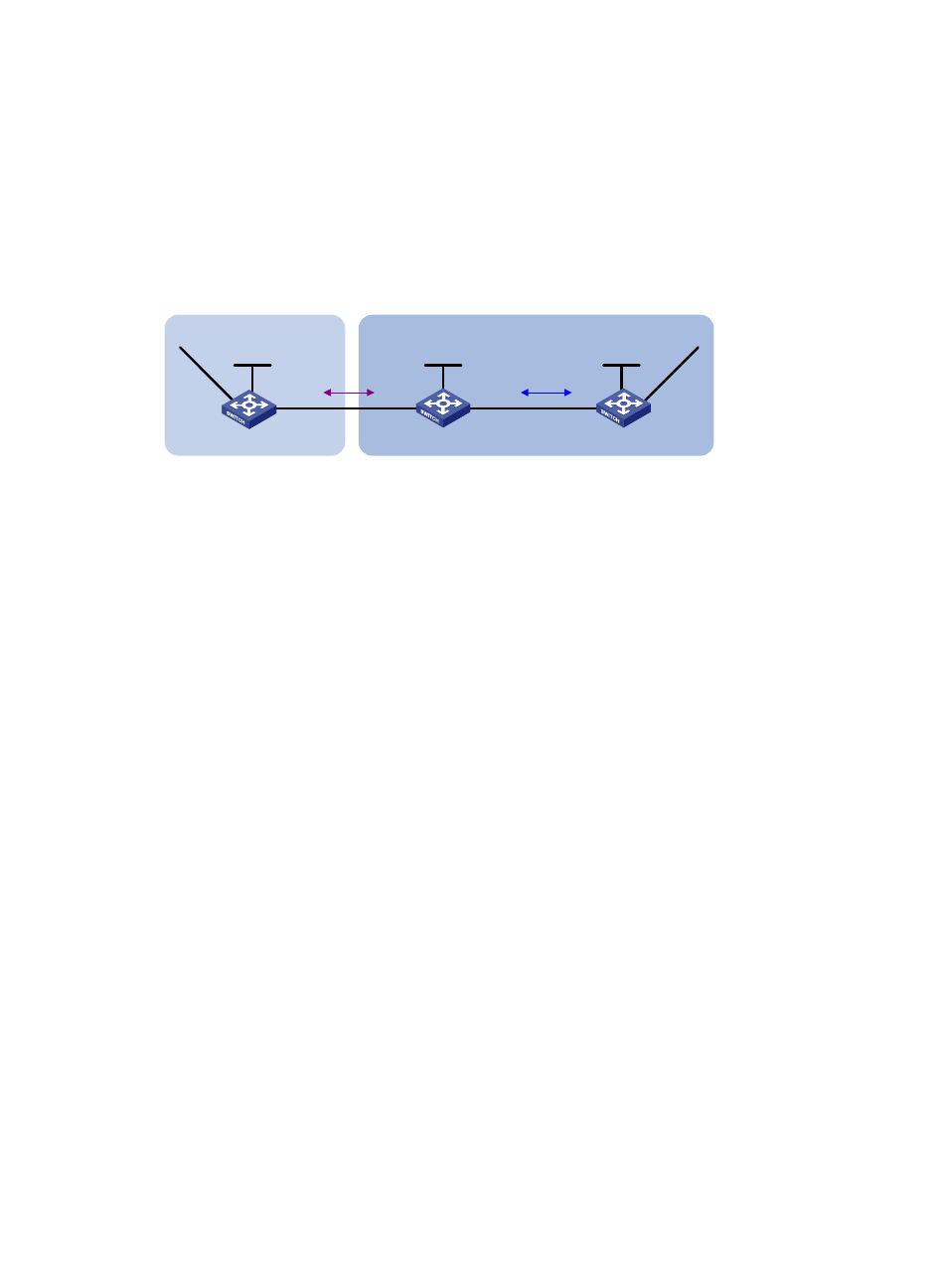
As shown in
, all devices of company A reside in AS 65008, and all devices of company B
reside in AS 65009. AS 65008 and AS 65009 are connected through Switch A and Switch B. It is
required that Switch A can access network 9.1.2.0/24 in AS 65009, and Switch C can access network
8.1.1.0/24 in AS 65008.
Figure 88 Network diagram
Configuration procedure
1.
Configure IP addresses for interfaces. (Details not shown.)
2.
Configure OSPF:
Enable OSPF in AS 65009, so Switch B can obtain the route to 9.1.2.0/24.
# Configure Switch B.
<SwitchB> system-view
[SwitchB] ospf 1
[SwitchB-ospf-1] area 0
[SwitchB-ospf-1-area-0.0.0.0] network 2.2.2.2 0.0.0.0
[SwitchB-ospf-1-area-0.0.0.0] network 9.1.1.0 0.0.0.255
[SwitchB-ospf-1-area-0.0.0.0] quit
[SwitchB-ospf-1] quit
# Configure Switch C.
<SwitchC> system-view
[SwitchC] ospf 1
[SwitchC-ospf-1] import-route direct
[SwitchC-ospf-1] area 0
[SwitchC-ospf-1-area-0.0.0.0] network 9.1.1.0 0.0.0.255
[SwitchC-ospf-1-area-0.0.0.0] quit
[SwitchC-ospf-1] quit
3.
Configure the EBGP connection:
Configure the EBGP connection and inject network 8.1.1.0/24 to the BGP routing table of Switch
A, so Switch B can obtain the route to 8.1.1.0/24.
# Configure Switch A.
<SwitchA> system-view
[SwitchA] bgp 65008
[SwitchA-bgp] router-id 1.1.1.1
[SwitchA-bgp] peer 3.1.1.1 as-number 65009
[SwitchA-bgp] network 8.1.1.0 24
Switch A
AS 65008
Vlan-int200
3.1.1.1/24
Switch C
Switch B
AS 65009
Vlan-int100
8.1.1.1/24
Vlan-int200
3.1.1.2/24
Vlan-int300
9.1.1.1/24
Vlan-int300
9.1.1.2/24
Loop0
1.1.1.1/32
Loop0
2.2.2.2/32
Loop0
3.3.3.3/32
EBGP
OSPF
Vlan-int400
9.1.2.1/24