Rip frr configuration example, Network requirements, Configuration procedure – H3C Technologies H3C S12500 Series Switches User Manual
Page 61
45
RIP FRR configuration example
Network requirements
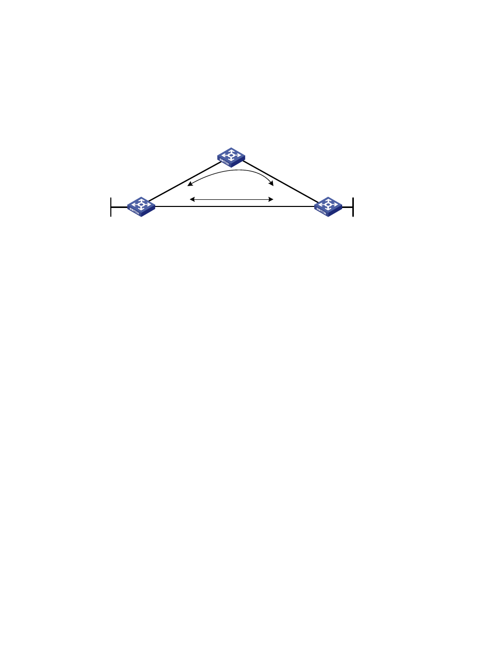
Switch S, Switch A, and Switch D are interconnected through RIPv2, as illustrated in
. When Link
A fails, services will be switched to Link B immediately.
Figure 14 Network diagram
Configuration procedure
1.
Configure IP addresses and subnet masks for interfaces on the switches. (Details not shown.)
2.
Configure RIPv2 on the switches to make sure Switch A, Switch D, and Switch S can communicate
with each other at Layer 3 and dynamic route update can be implemented among them with RIPv2.
(Details not shown.)
3.
Configure RIP FRR:
# Configure Switch S.
<SwitchS> system-view
[SwitchS] bfd echo-source-ip 1.1.1.1
[SwitchS] ip ip-prefix abc index 10 permit 4.4.4.4 32
[SwitchS] route-policy frr permit node 10
[SwitchS-route-policy] if-match ip-prefix abc
[SwitchS-route-policy] apply fast-reroute backup-interface vlan-interface 100
backup-nexthop 12.12.12.2
[SwitchS-route-policy] quit
[SwitchS] rip 1
[SwitchS-rip-1] fast-reroute route-policy frr
[SwitchS-rip-1] quit
# Configure Switch D.
<SwitchD> system-view
[SwitchD] bfd echo-source-ip 4.4.4.4
[SwitchD] ip ip-prefix abc index 10 permit 1.1.1.1 32
[SwitchD] route-policy frr permit node 10
[SwitchD-route-policy] if-match ip-prefix abc
[SwitchD-route-policy] apply fast-reroute backup-interface vlan-interface 101
backup-nexthop 24.24.24.2
[SwitchD-route-policy] quit
[SwitchD] rip 1
[SwitchD-rip-1] fast-reroute route-policy frr
[SwitchD-rip-1] quit45
4.
Verify the configuration:
Switch S
Switch D
Switch A
Loop 0
1.1.1.1/32
Vla
n-i
nt1
00
12
.12
.12
.1/
24
Vlan-int200
13.13.13.1/24
Vlan-int200
13.13.13.2/24
Vla
n-i
nt1
00
12
.12
.12
.2/
24
Vla
n-in
t10
1
24.2
4.2
4.2
/24
Vla
n-in
t10
1
24.2
4.2
4.4
/24
Loop 0
4.4.4.4/32
Link A
Link B