Configuration procedure – H3C Technologies H3C S12500 Series Switches User Manual
Page 55
39
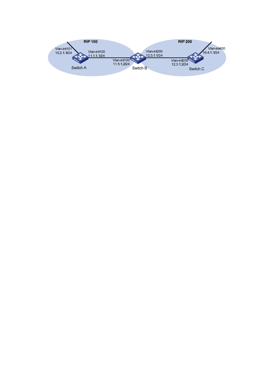
Figure 11 Network diagram
Configuration procedure
1.
Configure IP addresses for interfaces. (Details not shown.)
2.
Configure basic RIP:
# Enable RIP 100 and specify RIPv2 on Switch A.
<SwitchA> system-view
[SwitchA] rip 100
[SwitchA-rip-100] network 10.0.0.0
[SwitchA-rip-100] network 11.0.0.0
[SwitchA-rip-100] version 2
[SwitchA-rip-100] undo summary
[SwitchA-rip-100] quit
# Enable RIP 100 and RIP 200 and specify RIPv2 on Switch B.
<SwitchB> system-view
[SwitchB] rip 100
[SwitchB-rip-100] network 11.0.0.0
[SwitchB-rip-100] version 2
[SwitchB-rip-100] undo summary
[SwitchB-rip-100] quit
[SwitchB] rip 200
[SwitchB-rip-200] network 12.0.0.0
[SwitchB-rip-200] version 2
[SwitchB-rip-200] undo summary
[SwitchB-rip-200] quit
# Enable RIP 200 and specify RIPv2 on Switch C.
<SwitchC> system-view
[SwitchC] rip 200
[SwitchC-rip-200] network 12.0.0.0
[SwitchC-rip-200] network 16.0.0.0
[SwitchC-rip-200] version 2
[SwitchC-rip-200] undo summary
# Display the routing table of Switch C.
[SwitchC] display ip routing-table
Routing Tables: Public
Destinations : 6 Routes : 6
Destination/Mask Proto Pre Cost NextHop Interface
12.3.1.0/24 Direct 0 0 12.3.1.2 Vlan200
12.3.1.2/32 Direct 0 0 127.0.0.1 InLoop0
16.4.1.0/24 Direct 0 0 16.4.1.1 Vlan400