Alarms – Grass Valley NV8500 Series v.3.5 User Manual
Page 132
Advertising
116
Alarms
Making Alarm Connections
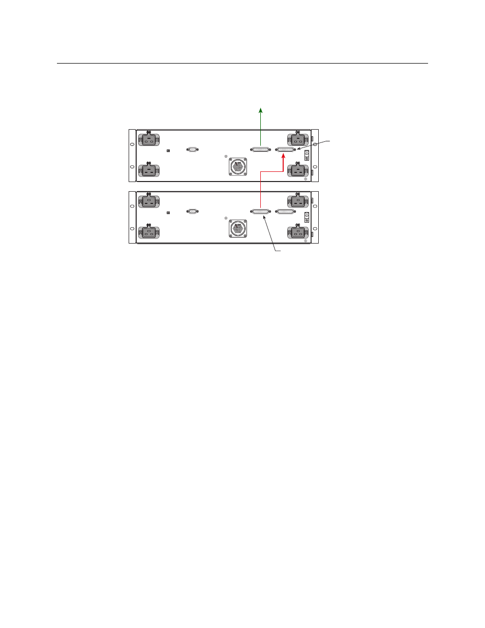
3 Connect PS Frame 1 Monitor of the second NV8300 frame to PS Frame 2 Monitor of the first
NV8300 frame, using a WC0046-00 cable.
Fig. 7-10: Power Monitor Connections for Two NV8300 Frames (Rear View)
Note also that the frame ID switches of the two power supply frames must be set differently.
PS Frame 1 Monitor
PS Frame 2 Monitor
NV8300 Power
Supply Frame 1
NV8300 Power
Supply Frame 2
to router power supply monitor connection
Advertising
This manual is related to the following products: