Installing i/o backplanes, To install an i/o backplane – Grass Valley NV8500 Series v.3.5 User Manual
Page 57
41
NV8500 Series
User’s Guide
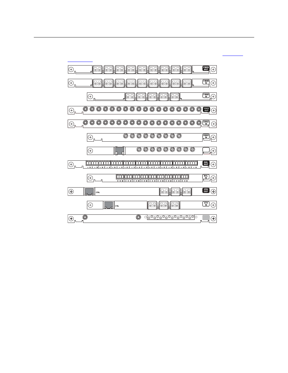
Figure 2-9 shows I/O backplanes, except for the expansion output backplanes used by the
NV8576-Plus. For information about the expanded NV8576-Plus, see Chapter 6,
Fig. 2-9: I/O Backplanes
Note that backplanes using DIN 1.0/2.3 or WECO connectors are passive; backplanes using SFP
(fiber optic) connectors have active circuitry.
Installing I/O Backplanes
Routers are delivered with all backplane modules installed. However, at some point you may
need to change backplanes. Before doing so, consult with Grass Valley Technical Support to
ensure proper operation.
To maintain proper airflow for cooling, all backplane slots must have either a backplane or cover
plate installed.
To Install an I/O Backplane
1 Facing the rear of the router, locate the slot into which the backplane is being installed.
2 Insert the backplane into the frame being sure to align the backplane’s printed circuit board
with the guides in the frame. Use gentle pressure at the top of the backplane to ensure the
backplane connector is fully mated with the motherboard.
Fiber Output
Fiber Input
Coax Output
Coax Input
AES Async Output
AES Async Input
Coax Input (NV8140)
Fiber Input (NV8140)
Coax Input (Frame Sync)
IP Gateway Input
IP Gateway Output
18
1
10
9
M3
OUT
M3 Output
COAX
IN