Physical connections, I/o connections, Configuration connection – Grass Valley NV8500 Series v.3.5 User Manual
Page 181: I/o connections configuration connection
165
NV8500 Series
User’s Guide
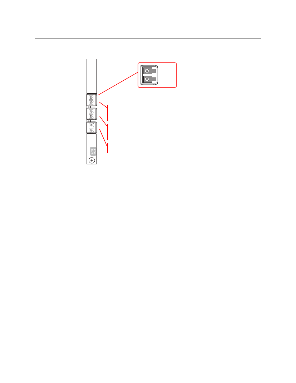
In the lower bays of the NV8576, backplane modules are installed “upside down” and the
ordering of the ports is slightly altered:
Fig. 11-2: SFP Connectors, in Lower Bays
The ordering is the same for the SFPs and for the video ports, but the clustering of the video
ports with respect to the SFPs is different. Also the output port of the SFP is at the top. In the
lower bays of the NV8576, SFP 1 carries video channels 1–2. SFP 2 carries video channels 3–5.
SFP 3 carries video channels 6–8.
Customers will use the RJ-45 port on the IP gateway cards to configure the cards. The IP address
of the backplane itself can be set in MRC. Once the IP address of the card is known, users can run
the browser application contained in the IP gateway card to specify the mapping of packetized
video streams to video ports.
The cards can use either of two different SFP modules. The short range modules are 850 nm;
long-range modules are 1310 nm.
Physical Connections
I/O Connections
I/O connections use 10GbaseSPF-SR (short range) or 10GbaseSFP-LR (long range) fiber optic
cables.
You can connect SFP ports either with crossover or through a 10GE switch.
Configuration Connection
The IP gateway cards reside in a slot of an input or output bay of an NV8140, NV8144, NV8280,
NV8576, or NV8576-Plus frame, with its matching backplane module.
The IP gateway card has an Ethernet port at its backplane. It is through this port that you can
configure the card’s video ports, using the card’s browser application.
Output
Input
SFP
1
2
3
SFP
n+1
n+2
Video
Ports
n+3
n+4
n+5
n+6
n+7
n+8