Nv8140, User’s guide – Grass Valley NV8500 Series v.3.5 User Manual
Page 25
9
NV8500 Series
User’s Guide
NV8140
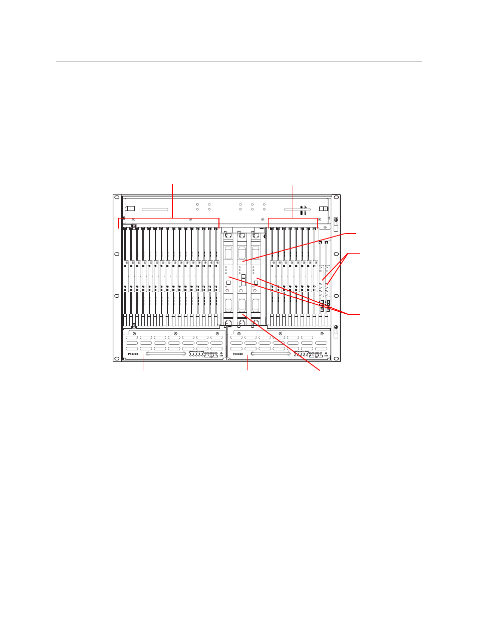
Figure 1-6 shows the front of the NV8140 (with the door removed). At the top of the frame is the
fan tray. Directly below the fan tray are card slots. On the far left are 16 output card slots. Near
the center of the frame, to the right of the output cards, are 3 crosspoint card slots. The first and
third slots hold the regular crosspoint cards. The middle slot holds a optional redundant cross-
point card.
To the right of the crosspoint card slots are 8 input card slots. To the right of the input card slots
are 2 slots for the primary and secondary control cards. Below the card slots, at the bottom of
the frame, are 2 bays for PS8300 power supply modules.
Fig. 1-6: NV8140 (Front View with Door Removed)
The NV8140 does not have a monitor card slot and does not support signal monitoring.
The NV8140 requires PS8300 power supplies, not PS 8100s.
The crosspoint card slots for the NV8140 are narrower than the crosspoint slots for the NV8144.
Do not attempt to install the older (and now obsolete) EM0799 or EM0819 crosspoint cards in
the NV8140. Physical damage will result.
Frame sync input cards are not available for the NV8140.
NV8144
FAN 1
AL
ARM
PO
W
ER
FAN 2
AL
ARM
PO
W
ER
FAN 3
AL
ARM
PO
W
ER
FAN 4
AL
ARM
PO
W
ER
FAN 5
AL
ARM
PO
W
ER
Input Cards (8)
Output Cards (16)
Control Cards (2)
Redundant Crosspoint Card
Power Supply
Fan
Crosspoint Cards (2)
Power Supply
Redundant Crosspoint Card