Nv8280, User’s guide – Grass Valley NV8500 Series v.3.5 User Manual
Page 27
11
NV8500 Series
User’s Guide
NV8280
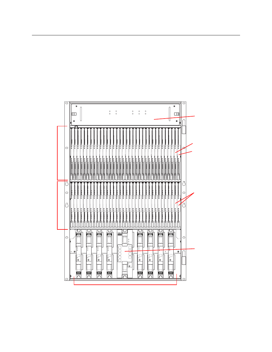
Figure 1-8 shows the front of the NV8280 (with the door removed). At the top of the frame is the
fan tray. Directly below are 32 output cards slots. Below the output cards are 32 input card slots.
To the far right of the output card slots are two additional slots for monitor cards. Similarly, to
the far right of the input card slots are two additional slots for the primary control card and
secondary control card.
Below the input card slots, at the bottom of the frame, are 10 crosspoint card slots. The middle 2
crosspoint card slots are for an optional redundant crosspoint. The other 8 slots are for cross-
point cards.
Fig. 1-8: NV8280 (Front View with Door Removed)
NV8280
144 X 144
3Gig
Redundant
XPT
STANDBY
PATH
LITE
ALARM
ACTIVE
POWER
REDUNDANT OPERATION
1
7
2
8
3
9
4
10
NV8500
NV8500
NV8500
NV8500
NV8500
NV8500
NV8500
NV8500
NV8500
Output
Cards (32)
Input
Cards (32)
Control Cards (2)
Crosspoint Cards (8)
Fan Tray
Output Monitor Card
Redundant
Crosspoint
Input Monitor Card