Ip gateway cards, Installing i/o cards, Ip gateway cards installing i/o cards – Grass Valley NV8500 Series v.3.5 User Manual
Page 73: Installing i/o cards in the nv8144 or nv8280
57
NV8500 Series
User’s Guide
Note that this is not required for MADI input.
IP Gateway Cards
See Chapter 11,
Installing I/O Cards
I/O cards slide into a (color-coded) card guide. Connectors at the rear of the card mate with
connectors on the motherboard. The ejector lever of each card is color-coded to match the color
of the card guides into which the card is to be inserted.
As you install cards, observe their LEDs:
If the ‘Valid Backplane’ LED on the card lights, the card and the backplane in the same slot match
correctly. You will probably want to verify that the ‘Good COM’ LED is on and the ‘Bad COM’ LED
is off. (For more details about LEDs,
Installing I/O Cards in the NV8144 or NV8280
1 Facing the front of the router frame, locate the card bays.
For the NV8144, see Figure 1-4 on page 7.
For the NV8280, see Figure 1-8 on page 11.
2 Insert input cards into the input card bay of the frame. Insert output cards into the output
bay. Use the card guides for reference:
•
Input cards go in slots with red card guides.
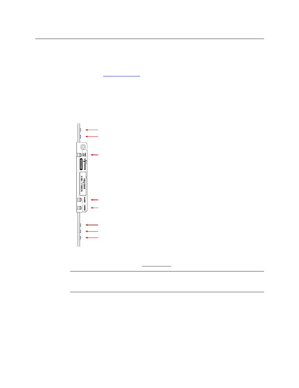
LED 7: Bad COM (red)
LED 5: FPGAs Loaded (yellow)
LED 4: Power (green)
LED 3: Alarm (red)
LED 2: Path Light (blue)
LED 11: Valid Backplane (green)
LED 12: Test (green)
LED 6: Good COM (green)
This illustration shows the front of a hybrid
3Gig/TDM (MADI) input card.
In general, there are many LEDS of different
colors across the circuit board. It is recommend
that you look only at the few LEDs at the very
front of the I/O card.
CAUTION
Do not drop, handle roughly, or stack circuit boards. If you cannot easily insert or remove a
board, stop and contact Grass Valley Technical Support.