Making power connections to the nv8280, Power, Connecting to power – Grass Valley NV8500 Series v.3.5 User Manual
Page 146: Ground lug power input
130
Power
Connecting to Power
5 Connect the router’s ground lug to earth ground using a copper wire (14–6 AWG). The
ground lug is located in the lower right corner at the rear of the frame.
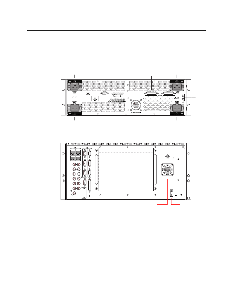
Making Power Connections to the NV8280
1 Facing the rear of the NV8300 power supply frame, connect one end of the WC0154-00
power cable to the large DC Output connector, shown here:
Fig. 8-12: NV8300 Power Supply Frame (Rear View)
2 Facing the rear of the NV8280, connect the other end of the WC0154-00 power cable to the
Power Input connection:
Fig. 8-13: NV8280 Power Supply Monitor and Power Connections (Rear View)
3 Still facing the rear of the NV8280, connect the ground lug to earth ground using a copper
wire from 14 to 6 AWG. The ground lug is located in the lower right corner of the frame.
4 Facing the rear of the NV8300 power supply frame, use a WC0157-00 power cable to connect
PS1 to an 20 A AC power source. In the U.S., these power cables have a twist-lock connector,
In other countries, the cable lacks a power connector and you must fabricate your own.
5 Repeat step 4 for PS3 and optionally for PS2 and PS4, that is for each remaining PS8300
power supply module to be installed.
6 After all power connections have been made, and only when you are ready to power-up the
router, face the front of the NV8300 power supply frame and insert a PS8300 in power mod-
PROFESSIONAL AUDIO
AND VIDEO EQUIPMENT
PS Frame 2 Monitor
PS1
PS2
PS4
PS3
Frame ID
Alarms
DC Output
PS Frame 1 Monitor
Ground Lug
10/100 BT
RTR EXP
10/100 BT
RTR EXP
VIDEO REF 1
PRI
SEC
CONTROL
CTRL 1
CTRL 2
CTRL 1
CTRL 2
DIA
G
(38.4 Kbaud)
DIA
G
(38.4 Kbaud)
VIDEO REF 2
AES REF 1
AES REF 2
RTR EXP IN
AL
ARMS
RTR EXP OUT
NVISION AUX BUS
POWER
SUPPLY
MONITORS
TIME CODE
E146905
POWER INPUT
PRI
SEC
Ground Lug
Power Input