Output, Setting the madi input card’s eq state, Eq is disabled. off – Grass Valley NV8500 Series v.3.5 User Manual
Page 71: User’s guide
55
NV8500 Series
User’s Guide
The MADI input stream can carry Dolby E pairs as well as AES pairs. Because the MADI stream is
locked to your house reference, Dolby E signals coming in faster or slower than the house refer-
ence will have samples added or dropped to match your house reference rate.
Each MADI signal is transformer-coupled to remove “noise” and forwarded to a MADI receiver.
The receiver extracts clock and data, removing any unnecessary synchronization information.
The signal is then forwarded to an audio TDM MUX and onward to the motherboard for
forwarding to the crosspoint cards.
Setting the MADI Input Card’s EQ State
You can configure the MADI input card so that it performs equalization (EQ) on the card’s MADI
signals. Normally EQ is enabled. Some installations might, however, require equalization
depending on the length of cables for the video signals. To set the EQ state for MADI input cards:
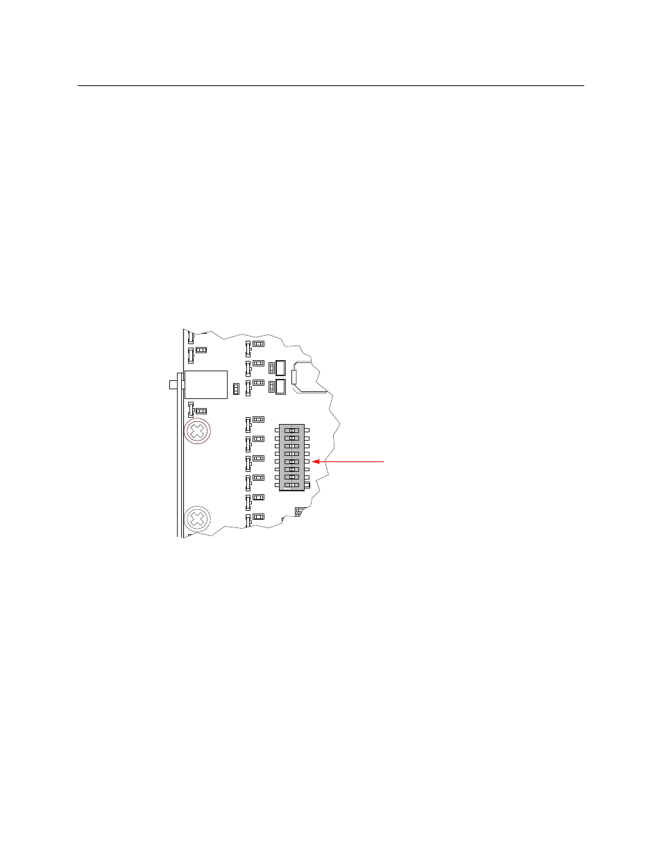
1 Locate the MADI input card to change.
2 Remove the card from the router frame.
3 Locate DIP switch 4:
4 Using a small, pointed object, such as a ball point pen, slide the switch to ON or OFF to con-
figure the equalization state:
ON
—
EQ is disabled.
OFF
—
EQ is enabled. (This is the default.)
5 Repeat for other MADI input cards you want to change.
Note that this is not required for MADI output.
Output
The MADI output card receives 16 video signals (SD, HD or 3Gig) from the crosspoint matrix and
up to 128 audio signals from the TDM matrix (via the motherboard) and forwards the signals to
its backplane’s connectors. The audio is multiplexed into two MADI streams, each stream and
the channel within the stream is selected based on the destination of the audio channel.
The output card’s TDM selector combines the audio channels into a single output and then
forwards the output to a MADI transmitter. The transmitter’s cable driver forwards the MADI
signal to its connector.
LOCK 1
LOCK 2
LOCK 3
LOCK 4
LOCK 5
LOCK 0
LED18
R23
R21
LED13
R20
R19
LED17
LED15
LED14
R22
R24
LED16
DIP SWITCH
0
1
PGOOD +
PATH LITE
LED2
R5
S2
A
R25
C
ON
R48
R46
R47
C14
R37
S1
R13
R43
R41
R42
U13
R4
U1
RX
TX
PGOOD +
VALID
BKPLN
PATH LITE
TEST
LED8
R2
LED2
C9
C10
LED11
C12
L3
LED10
LED9
LED12
R19
R18
R5
R16
R17
S2
R290
R3
C11
Switch 4 is near the front of the board, in the 4th
position on the DIP labeled S1.