Introduction, Overview of the routers – Grass Valley NV8500 Series v.3.5 User Manual
Page 24
8
Introduction
Overview of the Routers
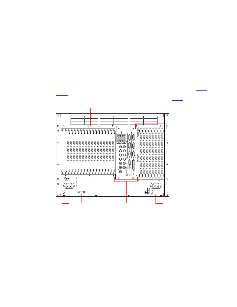
Figure 1-5 shows the rear of the NV8144. The farthest left-hand section is a blank plate that
corresponds in position to the control cards. Next to the control card plate are 16 input back-
plane slots. A mixture of different input cards and their backplane modules can be placed in
these slots.
The middle section contains system connections for audio reference, video reference, control
system connections, and power supply alarms.
To the right of the system connectors is one monitor backplane slot.
To the right of the monitor backplane are 8 output backplane slots. A mixture of different
output cards and their backplane modules can be placed in these slots.
At the very top of the frame is a grill for exhausting warm air dispersed by the fans. (See
on page 6.) Near the bottom of the frame are two AC power connectors. To the right of
the left-hand power connection is a power supply alarm connector. (See
Fig. 1-5: NV8144 (Rear View)
DIA
G
(38.
4 K
baud)
CONTROL
POWER
SUPPLY
i
MONITORS
TIME CODE
NVISION AUX BUS
RTR EXP OUT
RTR EXP IN
AES REF 1
AES REF 2
VIDEO REF 2
VIDEO REF 1
RTR EXP
10/100 BT
RTR EXP
10/100 BT
CTRL
1
CTRL
2
AL
ARMS
CTRL
1
CTRL
2
DIA
G
(38.
4 K
baud)
PRI
SEC
SEC
PRI
90-130V~/180-250V~
12.5A/6.25A
50/60Hz
1125 WATTS MAX
PS1
PS2
90-130V~/180-250V~
12.5A/6.25A
50/60Hz
1125 WATTS MAX
E146905
CNTRL NO. 9K50
PROFESSIONAL
VIDEO/AUDIO
ALARMS
Output Backplanes (8)
Input Backplanes (16)
Monitor Backplane (1)
Power Connector
Power
Connector
PS Alarm
Connector
System
Connectors