HEIDENHAIN TNC 320 (340 55x-04) Cycle programming User Manual
Page 386

386
Touch Probe Cycles: Automatic Workpiece Inspection
16.7 MEA
S
. RECT
AN. INSIDE (Cy
c
le 423, DIN/ISO: G423)
U
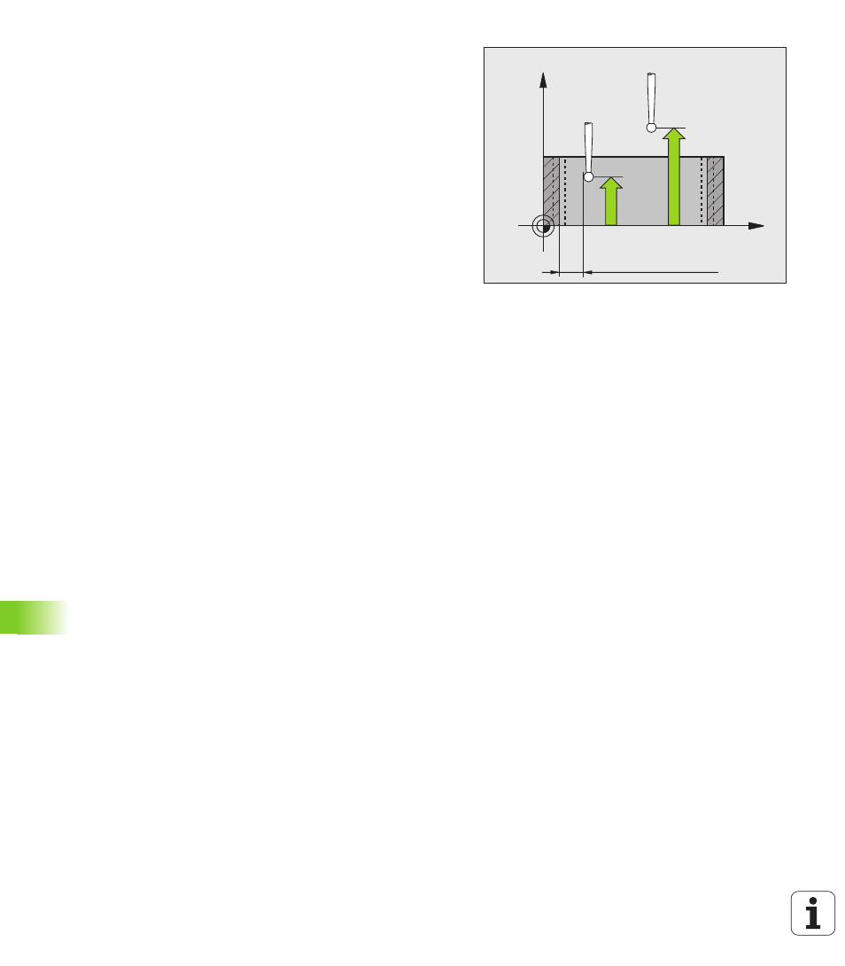
Setup clearance Q320 (incremental): Additional
distance between measuring point and ball tip. Q320
is added to SET_UP (touch probe table). Input range
0 to 99999.9999
U
Clearance height Q260 (absolute): Coordinate in the
touch probe axis at which no collision between touch
probe and workpiece (fixtures) can occur. Input range
–99999.9999 to 99999.9999
U
Traversing to clearance height Q301: Definition of
how the touch probe is to move between the
measuring points:
0: Move at measuring height between measuring
points
1: Move at clearance height between measuring
points
U
Max. size limit 1st side length Q284: Maximum
permissible length of the pocket. Input range 0 to
99999.9999
U
Min. size limit 1st side length Q285: Minimum
permissible length of the pocket. Input range 0 to
99999.9999
U
Max. size limit 2nd side length Q286: Maximum
permissible width of the pocket. Input range 0 to
99999.9999
U
Min. size limit 2nd side length Q287: Minimum
permissible width of the pocket. Input range 0 to
99999.9999
U
Tolerance for center 1st axis Q279: Permissible
position deviation in the reference axis of the working
plane. Input range 0 to 99999.9999
U
Tolerance for center 2nd axis Q280: Permissible
position deviation in the minor axis of the working
plane. Input range 0 to 99999.9999
X
Z
Q261
Q260
SET_UP(TCHPROBE.TP)
+
Q320