Jumper configuration – Precision Digital PD650 User Manual
Page 19
Model PD650 Large Display Process Meter
Instruction Manual
19
Jumper Configuration
Overview
Before programming the meter, it is necessary to configure three jumper arrays.
The jumper arrays are used for setting the type of input signal (4-20 mA, 0-5 V,
or 0-10 V); locking out the programmed settings, enable relay acknowledgement
(ACK), and setting relay fail-safe operation.
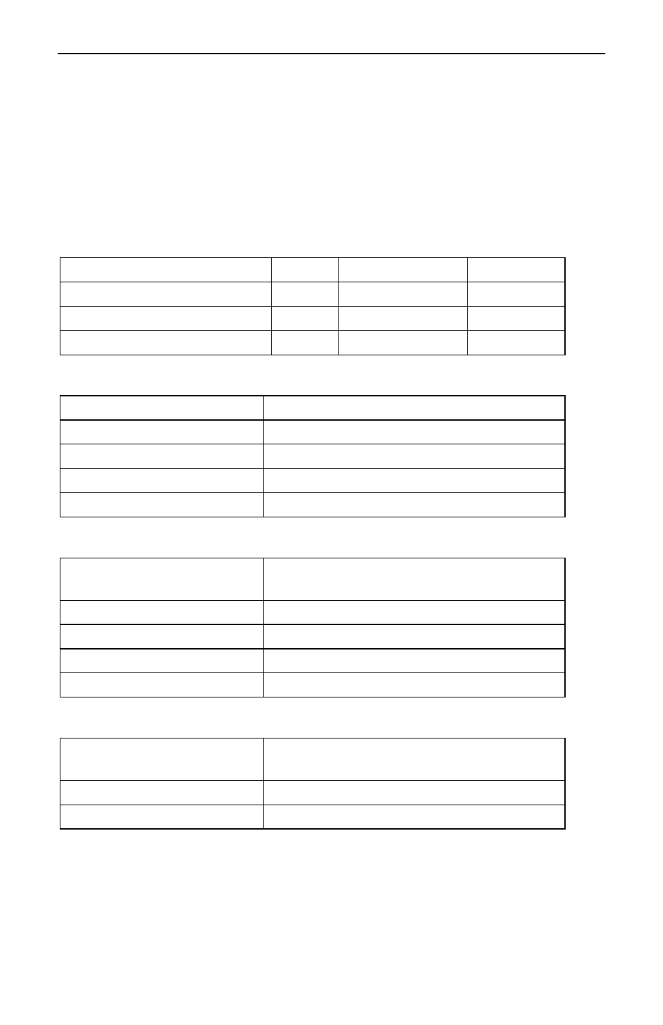
Jumper Arrays Function and Location
Jumper Array Function
Label
Location
Diagram
Input signal and Lockout
JP1
Main Board
Figure 3
Relay ACK enable
JP5
Display Board
Figure 14
Fail-safe
J5
Options Board
Figure 4
Input Selection and Lockout Jumpers
Jumper JP1 Position
Function
No jumper
Sets input to 5 V
20 mA
Sets input to 20 mA
10V
Sets input to 10 V
LOCK
Sets a lock on programming functions
Relay Acknowledge Enable
Jumper
JP5 Position
Function
1
Enable relay 1 manual reset
2
Enable relay 2 manual reset
3
Enable relay 3 manual reset
4
Enable relay 4 manual reset
Fail-Safe Operation of Relays
Jumper
J5 Position
Function
On
Apply fail-safe function to all relays
Off
Disable fail-safe function to all relays