Terminals designation, Wiring instructions – Precision Digital PD650 User Manual
Page 22
Model PD650 Large Display Process Meter
Instruction Manual
22
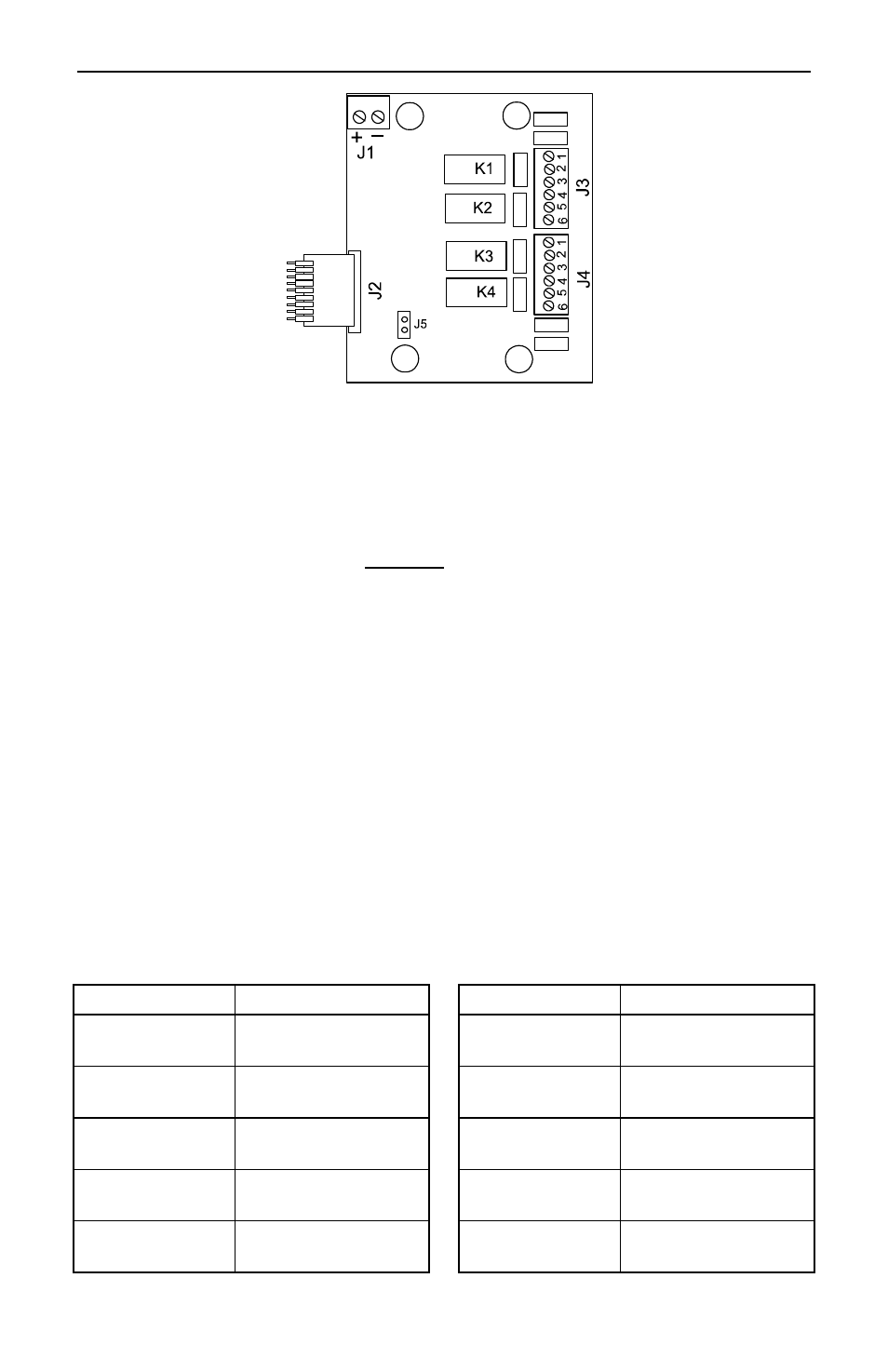
Figure 4.
Options Board Connectors and J5 Jumper
Wiring
Instructions
Refer to Figure 3 and Figure 4 for connectors’ location.
1. All field connections to be made with insulated copper wire, either solid or
stranded. Tighten all screw terminals to 4.5 lb-in (0.5 Nm).
Strip length = ¼ in (7 mm). DO NOT pre-treat wire with solder.
2. Terminals Earth Ground, L2(V-), L1(V+) on J2, Main Board and
terminals 1-6 on J3-J4, Options Board : Use AWG #12-18 wire, 600 volt,
60
°C. Connect only one wire to each terminal.
3. Terminals EN, AK, R, CM, S+, S-, P-, P+, P1-, P1+ on J1 Main Board and
terminals +, - on Options Board: Use AWG #12-22 wire, 150 volt, 60
°C. If
using AWG #20 or smaller wire, up to two wires may be connected to each
terminal. If using AWG #18 or larger wire, only one wire may be connected
to each terminal.
4. Install conduit hubs to the enclosure cable input ports. To maintain
NEMA 4X rating use only UL/CSA watertight conduit hubs.
5. Feed all wires through the enclosure cable input ports.
6. Remove one connector at a time from the headers and connect the wires to
the connector.
7. After wiring a connector, insert it back into the header.
Terminals Designation
Terminal Description
Terminal
Description
L1, L2, Gnd
AC input power
CM
Common (return) for
AK, EN, & R
V+, V-
DC input power
S+, S-
Input signal
EN
External Enter
P+, P-
P1+, P1-
24 VDC output
power supplies
AK External
relay
acknowledge
+, -
(Options Board)
4-20 mA output
(see page 26)
R
External total reset
1-6
(Option Board)
Relays 1-4
(see page 26)