Operation, Overview – Precision Digital PD650 User Manual
Page 64
Model PD650 Large Display Process Meter
Instruction Manual
64
OPERATION
Overview
This instrument is an analog input process meter with flow rate, totalizer, and
batch control capabilities. It accepts the common process signals such as
4-20 mA, 0-5 VDC, 1-5 VDC, and 0-10 VDC. It displays these signals in any
engineering unit on a 2.3" high, 4½ digit LED display for process/rate and six full
digits for total. The meter also provides two isolated 24 VDC power supplies to
drive both the input and output loops. Options include up to 4 relays for alarms or
batch control applications as well as an isolated 4-20 mA transmitter output.
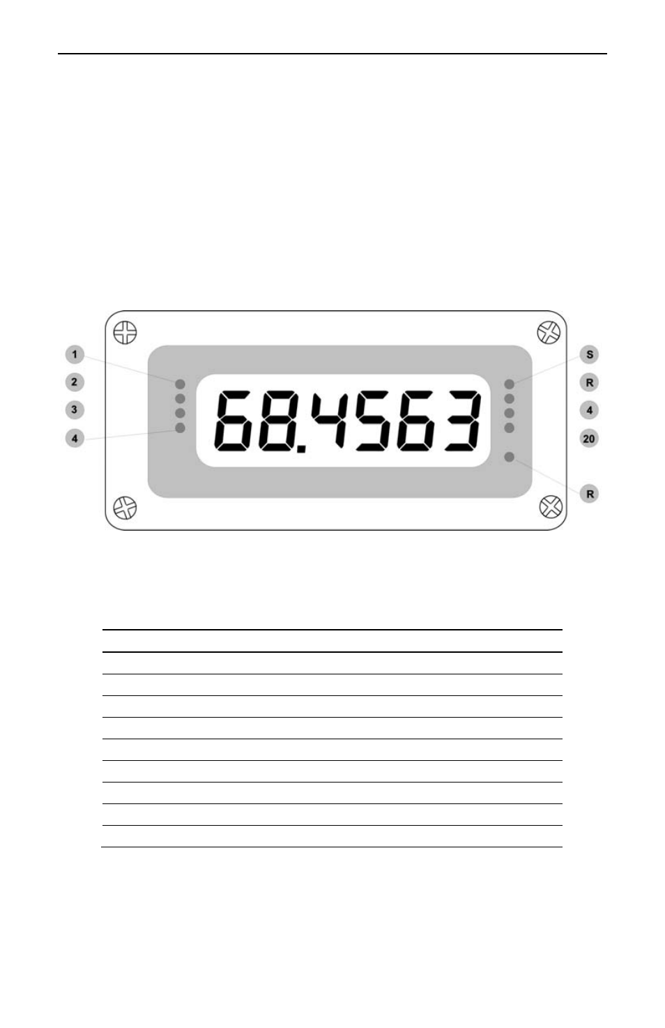
Figure 22. Front Panel LEDs
The front panel of the meter consists of six 2.3" high seven-segment LEDs as
well as nine programming/operational LEDs. The programming/operational LEDs
provide the following indication:
LED
During Programming
During Operation
1
Alarm 1
Alarm 1
2
Alarm 2
Alarm 2
3
Alarm 3
Alarm 3
4
Alarm 4
Alarm 4
S
Set point indicator
None
R
Reset point indicator
None
4
4 mA output indicator
None
20
20 mA output indicator
None
R Rate
indicator
Rate