Precision Digital PD650 User Manual
Page 48
Model PD650 Large Display Process Meter
Instruction Manual
48
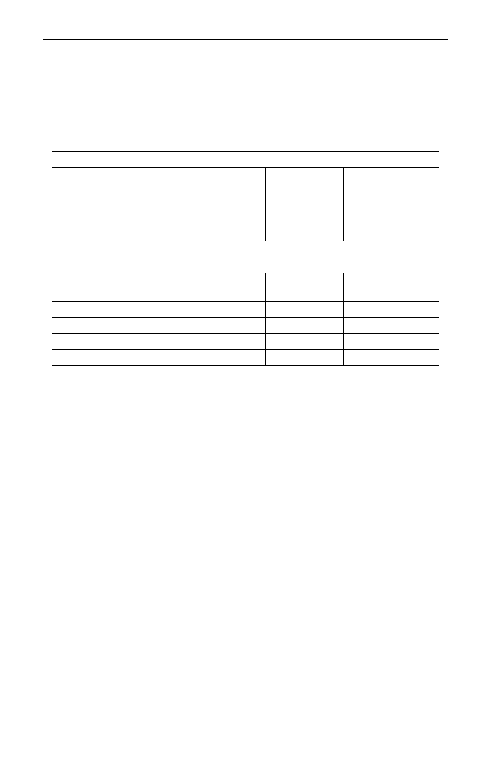
Set Relays for Manual or Automatic Reset
Jumper array JP5 located on the Display Board is used to program the relays so
they can be reset manually. See Figure 14 on page 29 for location of this jumper
array. This jumper array, in combination with SETuP functions of latching or non-
latching for process/rate and internal or external total reset, provide multiple relay
reset modes:
Relays Assigned to Total
Type of Reset
JP5 Jumper
Position
SETuP Menu
Automatic after delay elapses
N/A
Internal ( I )
Automatic when total resets to zero +
manual any time
On External
(
E )
Relays Assigned to Rate
Type of Reset
JP5 Jumper
Position
SETuP Menu
Automatic only after passing reset point
Off
Non-latching
Automatic + manual at any time
On
Non-latching
Manual only at any time
On
Latching
Manual only after passing reset point
Off
Latching
Set Relays for Fail-Safe Operation
In the fail-safe mode, the relay coils are energized and the Normally Open (NO)
contacts are connected to the Common (C) contacts under normal operation.
During an alarm condition, the relay coils are de-energized, the Normally Closed
(NC) contacts are connected to the Common (C) contacts. During a power failure
the relay contacts reflect an alarm condition.
Removing jumper J5 disables the fail-safe operation. J5 is located on the Options
Board next to J2 connector (see Figure 4, page 22). If fail-safe mode is disabled,
the operation of the relay contacts is opposite to the one described in the
previous paragraph.