Precision Digital PD650 User Manual
Page 32
Model PD650 Large Display Process Meter
Instruction Manual
32
Basic Meter Programming
Overview
The meter is programmed using three jumper arrays and the ENTER button. The
ENTER button is used to calibrate the meter, program various totalizer functions,
and set alarm set and reset points. The jumper arrays are used for programming
the input signal, lockout, relay fail-safe operation, and relay acknowledge enable.
If the optional relay board is installed, it is best to program the fail-safe jumper
(J5 on Options Board) for the desired operation before reassembling the Display
Board because this jumper is not accessible once the Display Board is installed.
There are four steps for programming the basic meter functions:
1. Select
Input
2. Perform Initial Calibration if Needed
3. Select Calibration Method
4. Calibrate or Scale the Meter
Select Input Signal
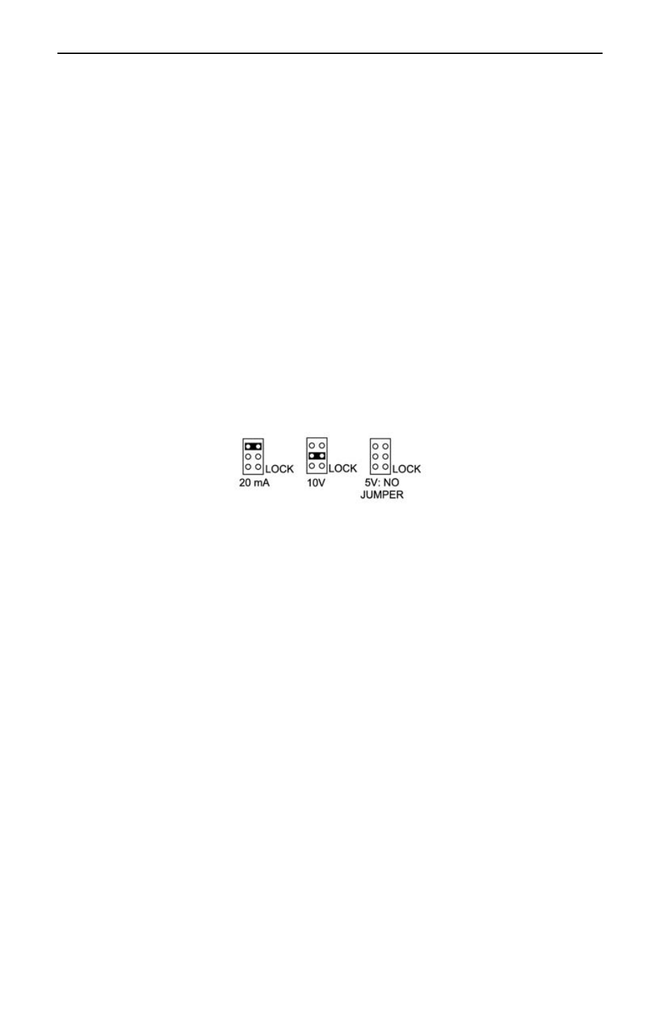
The meter can be programmed to accept all of the common process signals,
such as 4-20 mA, 1-5 V, 0-5 V, and 0-10 V using jumper array JP1 located on the
Main Board, to the right of the transformer.
Figure 16. JP1 Input Signal Selection Array.
The meter can also be programmed to restrict personnel from making changes to
the meter’s programming by installing a jumper over LOCK pins. For a complete
description of the Lockout and Display Selection Programming features, see
page 60.
Reassemble the Display Board
After the wiring and jumper selections have been made, reassemble the Display
Board.
The remaining setup and programming operations are performed with the
ENTER button.
If the meter contains relays, there is a fail-safe jumper (J5) that should be
addressed prior to reassembling the Display Board. Refer to the section Set
Relays for Fail-Safe Operation on page 48, for how to program this function of
the meter. This jumper is not accessible once the Display Board is in place.
To install the Display Board (see Figure 1, page 18):
1. Slide the Display Board under the top three screws. Make sure the ribbon
cable is connected to the connector on the Display Board.
2. Replace the bottom three mounting screws.
3. Fasten the top three mounting screws.
Access to JP1 is still possible with the Display Board mounted.