Altfp_convert signals, Altfp_convert signals -8, Altfp_convert – Altera Floating-Point User Manual
Page 123
ALTFP_CONVERT Signals
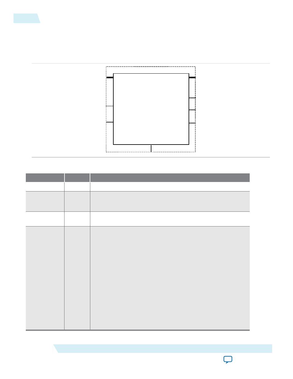
Figure 17-2: ALTFP_CONVERT Signals
dataa[]
clock
clk_en
inst
ALTFP_CONVERT
result[]
overflow
nan
underflow
aclr
Table 17-6: ALTFP_CONVERT Input Signals
Port Name
Required
Description
clock
Yes
The clock input to the ALTFP_CONVERT IP core.
clk_en
No
Clock enable that allows conversions to take place when asserted high.
When asserted low, no operation occurs and the outputs are
unchanged.
aclr
No
Asynchronous clear. The source is asynchronously reset when the
aclr
signal is asserted high.
dataa[]
Yes
Data input. The size of this input port depends on the
WIDTH_DATA
parameter value.
If the operation mode value is
INT2FLOAT
or
FIXED2FLOAT
, the data on
the input bus is an integer.
If the operation mode value is
FLOAT2INT
or
FLOAT2FIXED
, the input
bus is the IEEE floating-point representation. In the single-precision
format, the input bus width value is
32
. In the double-precision
format, the input bus width value is
64
.
In the single-extended precision format, the input bus range is from
43
to
64
.
If the operation mode value is
FLOAT2FLOAT
, the input bus value is the
IEEE floating-point representation. In the single-precision format, the
input bus width value is
32
. In the double-precision format, the input
bus width value is
64
. In the single-extended precision format, the
input bus range is from
43
to
64
.
17-8
ALTFP_CONVERT Signals
UG-01058
2014.12.19
Altera Corporation
ALTFP_CONVERT IP Core