Altera Floating-Point User Manual
Page 95
Related Information
•
Floating-Point IP Cores Design Example Files
on page 1-16
•
Provides the design example files for the Floating-Point IP cores
•
Provides information about installation, usage, and troubleshooting
ALTFP_LOG Design Example: Understanding the Simulation Results
The simulation waveform in this design example is not shown in its entirety. Run the design example files
in the ModelSim-Altera software to see the complete simulation waveforms.
These figures show the expected simulation results in the ModelSim-Altera software.
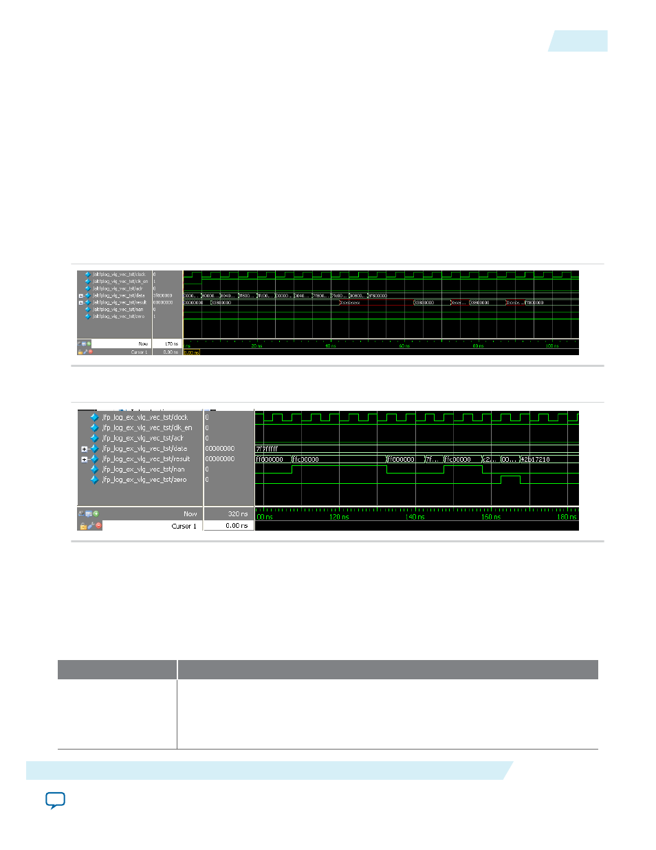
Figure 12-1: ALTFP_LOG ModelSim Simulation Waveform (Input Data)
Figure 12-2: ALTFP_LOG ModelSim Simulation Waveform (Output Data)
This design example includes the input of special cases to show the exception handling of the IP core,
such as the smallest valid input and the input value of “1”.
In this example, the output delay is set to 21 clock cycles. Therefore, the result is only shown at the output
port after the 21st clock cycle at 102.5 ns.
Table 12-4: Summary of Input Values and Corresponding Outputs
This table lists the inputs and corresponding outputs obtained from the simulation in the waveforms.
Time
Event
0 ns, start-up
data[]
value: 0000 0000h
Output value: An undefined value is seen on the
result[]
port, which is ignored.
All values seen on the output port before the 21st clock cycle are merely due to the
behavior of the system during start-up and should be disregarded.
UG-01058
2014.12.19
ALTFP_LOG Design Example: Understanding the Simulation Results
12-3
ALTFP_LOG
Altera Corporation