Out-of-band flow control block clocks – Altera Interlaken MegaCore Function User Manual
Page 32
4–6
Chapter 4: Functional Description
Clocking and Reset Structure
Interlaken MegaCore Function
June 2012
Altera Corporation
User Guide
Out-of-Band Flow Control Block Clocks
If you turn on Enable out-of-band flow control, your Interlaken MegaCore function
has the following four additional clock domains:
■
rx_oob_in_fc_clk
—clocks the incoming out-of-band flow control interface signals
described in the Interlaken specification. This clock is received from an upstream
TX out-of-band flow control block associated with the Interlaken link partner.
■
tx_oob_out_clk
—clocks the outgoing out-of-band flow control interface signals
described in the Interlaken specification. This clock is generated by the
out-of-band flow control block and sent to a downstream RX out-of-band flow
control block associated with the Interlaken link partner.
■
rx_oob_in_sys_clk
—clocks the outgoing calendar and status information on the
application side of the block. The frequency of this clock must be at least double
the frequency of rx_oob_in_fc_clk.
■
tx_oob_in_double_fc
—clocks the incoming calendar and status information on
the application side of the block. The frequency of this clock must be double the
frequency of tx_oob_out_clk.
Clock Diagrams for the Interlaken MegaCore Function
to
show the clock diagrams for the Interlaken MegaCore
function variations with the supported numbers of lanes. The figures show variations
with transceivers. For figures that show variations without transceivers, refer to
Appendix B, Excluding Transceivers for Faster Simulation
The 10-lane and 20-lane variations use the transceivers in PMA Direct mode. These
variations incorporate five lanes in a single transceiver block. The other variations use
the transceivers in low latency PCS mode, incorporating four lanes in each transceiver
block.
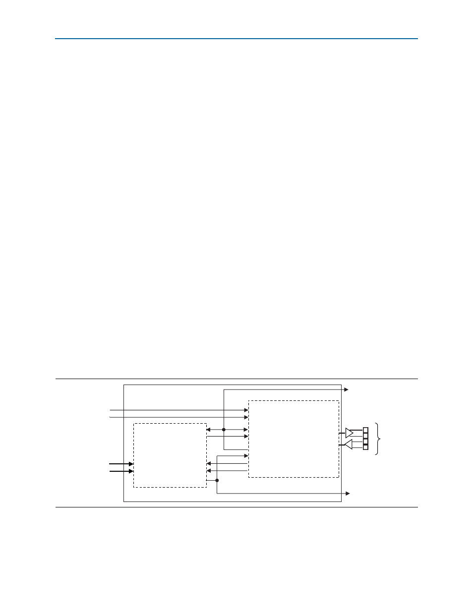
shows the clock diagram for a four-lane Interlaken MegaCore function.
Figure 4–2. Clock Diagram for 4-Lane Interlaken MegaCore Function
cal_blk_clk
ref_clk
cal_blk_clk
ref_clk
clk_in
tx_datain[79:0]
clk_out (master TX clock)
common_rx_clk
rx_dataout[79:0]
rx_clk[3:0]
tx_pin[3:0]
rx_pin[3:0]
tx_lane_clk
tx_data [79:0]
rx_data [79:0]
rx_lane_clk
[3:0]
common_rx_coreclk
HSIO Bank 0
(low latency PCS mode)
tx_coreclkout
rx_coreclkout
x4
tx_mac_clk
rx_mac_clk
tx_mac_clk
rx_mac_clk
TX MAC and PCS
RX MAC and PCS