Fifo buffers and pipeline registers, Transceivers – Altera Interlaken MegaCore Function User Manual
Page 49
Chapter 4: Functional Description
4–23
High-Speed I/O Block
June 2012
Altera Corporation
Interlaken MegaCore Function
User Guide
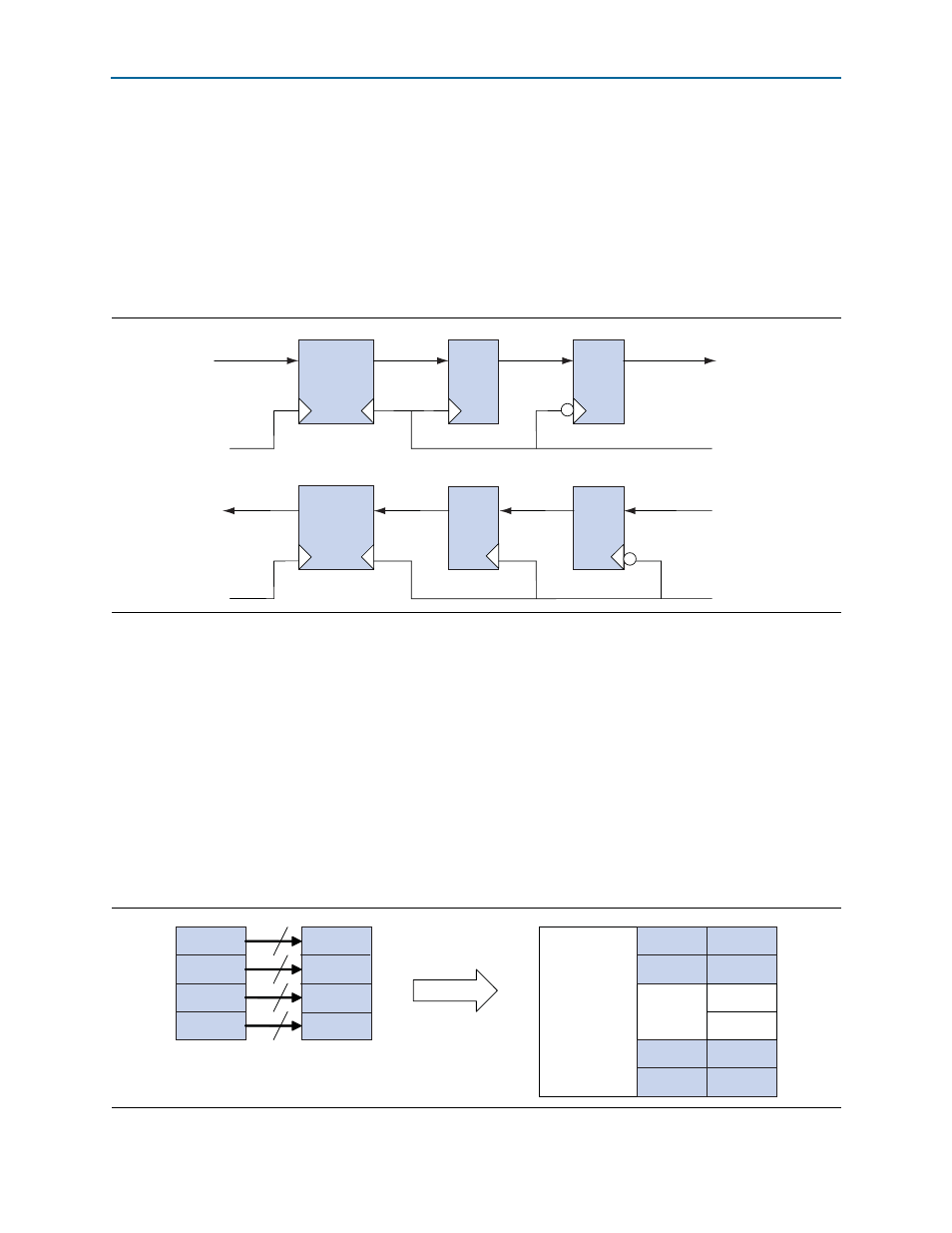
FIFO Buffers and Pipeline Registers
Achieving timing closure can be difficult for the 10- and 20-lane Interlaken variations,
which use the Stratix IV transceivers in PMA Direct mode. To resolve timing issues
between the PMA Direct SERDES block in the transceiver and the Interlaken
MegaCore function, the FIFO buffer and pipeline registers block is instantiated for
variations that use PMA Direct mode. The block includes a two-stage register pipeline
and a clock-crossing FIFO buffer.
shows the receive and transmit paths
through this block.
The pipelines are clocked by a global clock on the PCS side and a periphery clock on
the transceiver side.
Transceivers
In 10- and 20-lane Interlaken MegaCore function variations, the Stratix IV transceivers
are configured in PMA Direct mode. In all the other variations, the transceivers are
configured in low latency PCS mode. Refer to the clock diagrams in
for the Interlaken MegaCore Function” on page 4–6
for information about how the
transceiver bank clock and data lines are connected in the different variations.
show how the Interlaken MegaCore function uses the
individual transceivers in each transceiver block, depending on the variation.
Figure 4–17. FIFO Buffer and Pipeline Registers Block
FIFO
Buffer
FIFO
Buffer
From
TX PCS Block
To
RX PCS Block
t x_clkout (PCLK)
rx _clkout (PCLK)
GCLK from core
GCLK from core
From RX Transceiver
To TX Transceiver
Figure 4–18. Transceiver Block Use in 4-, 8-, and 12-lane Variations
lane
lane
lane
lane
20
20
20
20
FPGA
PCS
PCS
PCS
PCS
PMA
PMA
PMA
PMA
PMA
PMA
ALTGX
ALTGX
ALTGX
ALTGX