Channel filtering blocks, Packet regrouper, Channel filtering blocks –19 packet regrouper –19 – Altera Interlaken MegaCore Function User Manual
Page 45
Chapter 4: Functional Description
4–19
Receive Path
June 2012
Altera Corporation
Interlaken MegaCore Function
User Guide
Channel Filtering Blocks
Each channel filtering block identifies the data that targets the channel with which it is
associated. It identifies the target channel of a burst from the burst control words. The
channel filtering block passes that data through to a regrouper, filtering out the data
that targets the other channel. As the channel filter filters the data, it rearranges each
data sample so that the valid data and idle bytes for its associated channel are the
most significant bytes.
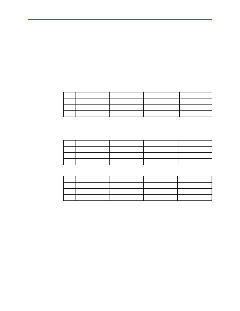
The following example illustrates the function of the channel filtering blocks in a
variation with a 256-bit channel width.
shows example four-word-wide raw
data output from the RX MAC block. Each table cell represents a 64-bit word.
shows the resulting output stream from the RX channel 0 filter and
shows the resulting output stream from the RX channel 1 filter.
Packet Regrouper
The packet regrouper for each channel receives the filtered data and rearranges each
channel data sample so that the valid bytes are the most significant bytes, removing
all control words. The information is instead conveyed by using the
rx_chX_dataout_empty
vector to indicate the number of invalid bytes on the
rx_chX_dataout_data
bus in the current rx_mac_c_clk clock cycle. Any
start-of-packet and end-of-packet information is likewise conveyed in separate
signals, rx_chX_dataout_startofpacket and rx_chX_dataout_endofpacket, which
are asserted during the clock cycle in which the appropriate condition holds.
The packet regrouper signals the application channel that it has data ready for
transmission on the channel, by asserting the rx_chX_dataout_valid signal after it
loads the data on the rx_chX_dataout_data bus. Refer to
the channel data bus width.
Table 4–6. Example Raw Data Output From RX MAC Block
t = 0
BC SOP ch0
Data 0
Data 1
Data 2
t = 1
Data 3
Data 4
BC EOP ch0, SOP ch1
Data 5
t = 2
Data 6
Data 7
Data 8
Data 9
t = 3
Data 10
Data 11
IDLE EOP ch1
—
Table 4–7. Output Stream From RX Channel 0 Filter
t’= 0
BC SOP ch0
Data 0
Data 1
Data 2
t’ = 1
Data 3
Data 4
BC EOP ch0
—
t’ = 2
—
—
—
—
t’ = 3
—
—
—
—
Table 4–8. Output Stream From RX Channel 1 Filter
t" = 0
—
—
—
—
t" = 1
BC SOP ch1
Data 5
—
—
t" = 2
Data 6
Data 7
Data 8
Data 9
t" = 3
Data 10
Data 11
IDLE EOP ch1
—