Core latency, Core latency -14, And the – Altera SerialLite III Streaming MegaCore Function User Manual
Page 38: Related information, Tx_serial_clk, Tx_pll_locked, 14 core latency
Note: The core operates at higher clock rates in Advanced Clocking Mode. Therefore, when operating in
this mode, it may be difficult to close timing at higher data rates (e.g., 12 to 15 G) and/or number
of lanes.
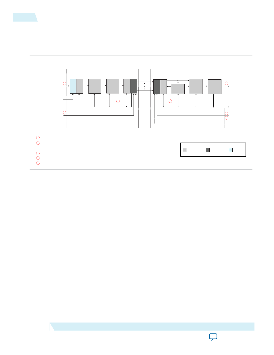
Figure 4-9: SerialLite III Streaming IP Core Block Diagram in Advanced Clocking Mode
SerialLite III
Streaming
Link
Application
Module
PPM-Absorption
Module
Adaptation
Module
Native PHY or
Interlaken PHY
IP Core
SerialLite III
Streaming Source Core
Source
User
Interface
Source
User
Clock
Core Clock
Transceiver
Reconfiguration
Clock
Core Clock
SerialLite III
Streaming Sink Core
Lane
Alignment
Module
Adaptation
Module
Application
Module
Sink
User
Interface
Sink
Interface Clock
Transceiver
Reference Clock
Transceiver
Reconfiguration
Clock
1
1
4
3
2
2
1
4
3
2
For data rates ≤ 15.625 Gbps (Arria 10, Stratix V, and Arria V GZ devices), the Native PHY or Interlaken PHY IP core generates the core clock
(serial data rate /40)—tx_clkout at the source core and rx_clkout at the sink core. For data rates > 15.625 Gbps and ≤ 17.4 Gbps, (Arria 10 devices), the
Native PHY or Interlaken PHY IP core generates the core clock (serial data rate /64)—tx_clkout at the source core and rx_clkout at the sink core.
The source user interface is derived through the source user clock.
The sink user interface is driven through the sink interface clock.
For Stratix V and Arria V GZ devices, the transceiver reference clock is provided to the Interlaken PHY IP core.
For Arria 10 devices, the transmit serial clock (tx_serial_clk) is provided to the Native PHY IP Core for TX only.
Transceiver Reference Clock
or Transmit Serial Clock
Core Clock
Domain
Transceiver
Clock Domain
User Clock
Domain
Legend
5
For RX into the Native PHY or Interlaken PHY IP core, the transceiver reference clock is only provided as a parameter.
5
Native PHY or
Interlaken PHY
IP Core
Note: The SerialLite III Streaming IP core uses the transmit serial clock bus (
tx_serial_clk
) and the
tx_pll_locked
signal to connect the external transmit PLL to the Arria 10 Native PHY IP core.
Related Information
Transmission Overheads and Lane Rate Calculations
on page 4-15
Core Latency
The table below lists the latency measurement for the SerialLite III Streaming duplex core in standard and
advanced clocking mode. An average value is taken from a set of samples during hardware testing.
For a loopback scenario, the core latency measurement is based on the round trip latency from the TX
core input to RX core output.
4-14
Core Latency
UG-01126
2015.05.04
Altera Corporation
SerialLite III Streaming IP Core Functional Description