Altera SerialLite III Streaming MegaCore Function User Manual
Page 48
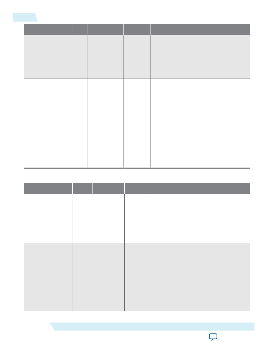
Signal
Width
Clock Domain
Direction
Description
end_of_burst
1
Standard
clocking: user_
clock
Advanced
clocking: core_
clock
Output
When the core is in burst mode operation,
assertion of this signal indicates that the
information on the data vector is the end of a
burst.
error
N+5
Standard
clocking: user_
clock
Advanced
clocking: core_
clock
Output
This vector indicates the state of the sink
adaptation module’s FIFO buffer. N
represents the number of lanes:
• [N+4]: An SEU error occurred and could
not be corrected (ECC enabled); Don't
care (ECC disabled)
• [N+3]: An SEU error occurred and was
corrected (ECC enabled); Don't care
(ECC disabled)
• [N+2]: FIFO buffer overflow
• [N+1]: FIFO buffer underflow
• [N]: Loss of alignment
• [N-1:0]: RX CRC 32 error
Table 4-8: SerialLite III Streaming IP Core Duplex Core Signals
Signal
Width
Clock Domain
Direction
Description
tx_serial_clk
N
N.A.
Input
This high-speed serial clock input from the
external transceiver PLL. The width is the
same as the number of lanes specified in the
parameter editor. Each bit of the vector
corresponds to serial clock of the transmit
channel. (Arria 10 devices only)
N represents the number of lanes.
tx_pll_locked
1
N.A.
Input
This signal indicates that all external
transceiver PLLs are locked. If more than one
external transceiver PLL is required for
higher lanes, each instantiation outputs a bit
that indicates whether the PLL providing the
high-speed clock for a corresponding
transceiver has achieved its lock status. The
pll_locked
output signal from the external
transceiver PLLs should be ANDed together
before being input to the IP core. (Arria 10
devices only)
4-24
Signals
UG-01126
2015.05.04
Altera Corporation
SerialLite III Streaming IP Core Functional Description