Signals, Signals -19, Input (see – Altera SerialLite III Streaming MegaCore Function User Manual
Page 43
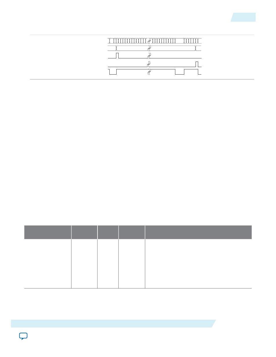
Figure 4-14: Sink Waveform for Continuous Mode
data[127:0]
sync[7:0]
start_of_burst
end_of_burst
valid
0
8
*
18*
d
8
•
start_of_burst
pulses for one clock cycle, indicating that the data burst starts at that clock cycle.
•
end_of_burst
pulses for one clock cycle, indicating that the data burst ends at that clock cycle.
• The
valid
signal indicates valid data. It is turned off between two data bursts that are between the
current data burst's
end_of_burst
clock cycle and the next data burst's
start_of_burst
clock cycle.
The valid signal can be pulled low in the middle of a data burst after a data burst's
start_of_burst
and before the data burst's
end_of_burst
, indicating non-valid data at that clock cycle.
• The
sync
vector is used in burst mode. The sync data picked up at the source's
start_of_burst
high
cycle is sent out at the sink as shown in the waveform. Multiple logical channel is time-multiplexed
into physical channels. Sync vector can be used to store the logical channel number that the burst
targets. The logical channel number is multiplexed into the sync vector during the
start_of_burst
.
The value is embedded into the data and sent over to the receiving party. The sink can extract the
channel number from
start_of_burst
data bus to output on the sync vector of the sink. The sync
vector can also be used to include empty information which indicates invalid data at the
end_of_burst
. In this case, the empty value is multiplexed into the sync vector during
end_of_burst
.
The data is again embedded inside and sent over to the receiving party. The sink extracts the informa‐
tion and output on the sync vector of the sink.
Signals
The following tables list all the input and output signals of the SerialLite III Streaming IP core.
Table 4-6: SerialLite III Streaming IP Core Source Core Signals
Signal
Width
Clock
Domain
Direction
Description
tx_serial_clk
N
N.A.
Input
This high-speed serial clock input from the
external transceiver PLL. The width is the same
as the number of lanes specified in the
parameter editor. Each bit of the vector
corresponds to serial clock of the transmit
channel. (Arria 10 devices only)
N represents the number of lanes.
UG-01126
2015.05.04
Signals
4-19
SerialLite III Streaming IP Core Functional Description
Altera Corporation