Figure 2–1, Table 2–1 – Altera Cyclone III Development Board User Manual
Page 12
2–2
Chapter 2: Board Components
Board Overview
Cyclone III 3C120 Development Board Reference Manual
© March 2009 Altera Corporation
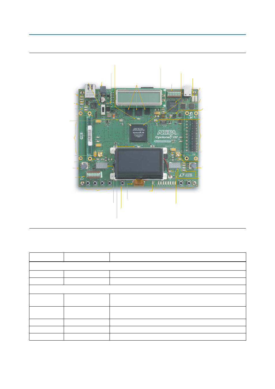
describes the components and lists their corresponding board references.
Figure 2–1. Top View of the Cyclone III Development Board
Speaker Header (J5)
DC Power
Jack (J2)
Ethernet PHY
LEDs (D1, D3, D4)
Ethernet PHY
Duplex LED (D6)
Power
Switch (SW2)
Power
LED (D5)
Ethernet PHY TX/RX
Activity LEDS (D7, D8)
MAX II CPLD (U7)
DDR2 SDRAM Device Interface
Four x16 and one x8
(U11, U12, U25, U26, U13)
(Three on Top and Two on Bottom)
DDR2TOP_ACTIVE
LED (D11)
Cyclone III FPGA (U20)
MAX II Device
Control DIP
Switch (SW1)
24-MHz Crystal (Y1)
6-MHz
Crystal (Y2)
Clock Out SMA (J11)
HSMC Port B
Present LED (D19)
PGM Config Select
Rotary Switch (SW5)
User Push Buttons
(S1 through S4)
User DIP
Switch (SW6)
CPU Reset Push
Button Switch (S5)
Power Select
Rotary Switch (SW4)
User Defined
7-Segment
Display (U30)
Board-Specific LEDs
(D20 through D24)
SRAM Active
LED (D17)
HSMC Port A
Present LED (D18)
Clock In SMA (J10)
Power Display (U28)
Flash Active
LED (D23)
Configuration
Done LED (D25)
User LEDs
(D26 through D33)
Reset and
Factory
Configuration
Push Buttons
(S6 and S7)
DDR2BOT_ACTIVE
LED (D16)
50-MHz
Clock (Y5)
125-MHz
Clock (Y4)
24-MHz USB-
Blaster Clock (Y3)
JTAG Control
DIP Switch (SW3)
Graphics
LCD (J13)
HSMC Port B (J9)
(Debug Header Shown)
HSMC Port A (J8)
(Loopback Board Shown)
Device Select
Jumper (J6)
Table 2–1. Cyclone III Development Board (Part 1 of 3)
Board Reference
Type
Description
Featured Devices
U20
FPGA
EP3C120, 780-pin FineLine BGA package.
U7
CPLD
EPM2210G, 256-pin device in a FineLine BGA package.
Configuration Status and Setup Elements
J6
Device select
(DEV_SEL) jumper
Sets target device for JTAG signals when using an external USB-Blaster or
equivalent.
J3
Input
Type B USB connector that allows for connecting a Type A-B USB cable
between a PC and the board.
D20 through D24
User LEDs
Board-specific configuration green LEDs.
D25
Configuration done LED
Green LED that illuminates when the FPGA is successfully configured.
D12 through D15
Channel activity LEDs
Green LEDs that indicate the RX and TX activity on the HSMC Ports A or B.