Configuration, status, and setup elements, Configuration, status, and setup elements –14, Note 1) – Altera Cyclone III Development Board User Manual
Page 24
2–14
Chapter 2: Board Components
Configuration, Status, and Setup Elements
Cyclone III 3C120 Development Board Reference Manual
© March 2009 Altera Corporation
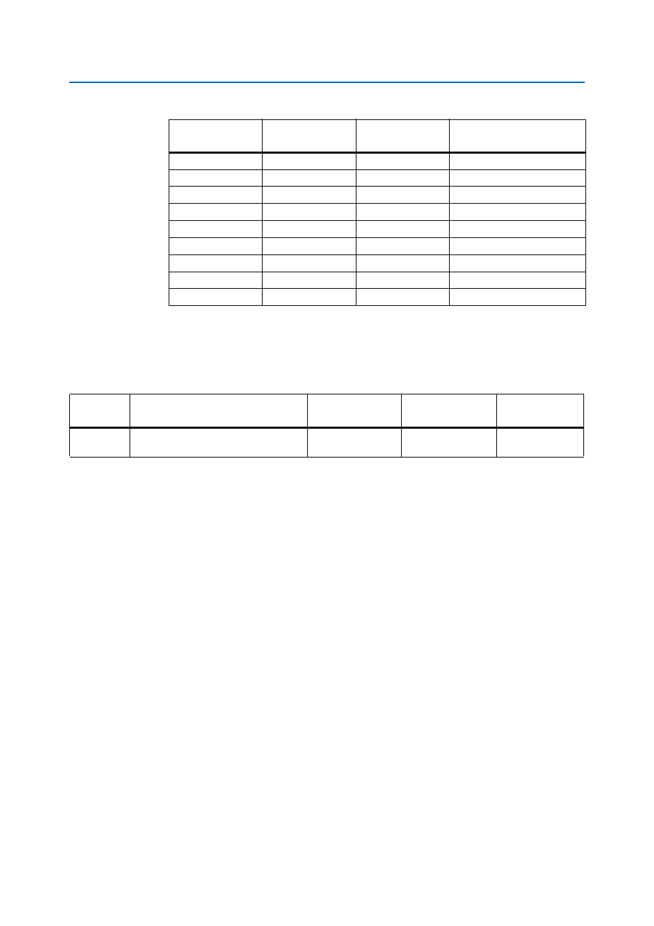
lists the MAX II component reference and manufacturing information.
Configuration, Status, and Setup Elements
This section describes the board’s configuration, status, and setup elements, and is
divided into the following groups:
■
■
FPGA programming over USB
■
FPGA programming from flash memory
■
Flash programming over USB
■
“Status Elements” on page 2–17
■
Board-specific LEDs
■
Power display
■
■
JTAG control DIP switch
■
MAX II device control DIP switch
■
System reset and configuration push buttons
■
POWER SELECT rotary switch
■
PGM CONFIG SELECT rotary switch
■
Speaker header
C16
—
Power
VCCIO3
H11
—
Power
VCCIO3
J11
—
Power
VCCIO3
P16
—
Power
VCCIO3
L8
—
Power
VCCIO4
L9
—
Power
VCCIO4
T3
—
Power
VCCIO4
T14
—
Power
VCCIO4
P15
1.8 V
Input
VOLTS_WATTS
Note to
(1) For more information about the MAX II pin-out, refer to the Altera website at
.
Table 2–5. MAX II Device Pin-Out
(Note 1)
(Part 8 of 8)
MAX II Pin Number
I/O Standard
Signal Direction
Schematic
Signal Name
Table 2–6. MAX II Component Reference and Manufacturing Information
Board
Reference
Description
Manufacturer
Manufacturing
Part Number
Manufacturer
Website
U7
256-pin device in a FineLine Ball Grid
Array (FBGA) package
Altera Corporation
EPM2210GF256C3N