Altera Cyclone III Development Board User Manual
Page 30
2–20
Chapter 2: Board Components
Configuration, Status, and Setup Elements
Cyclone III 3C120 Development Board Reference Manual
© March 2009 Altera Corporation
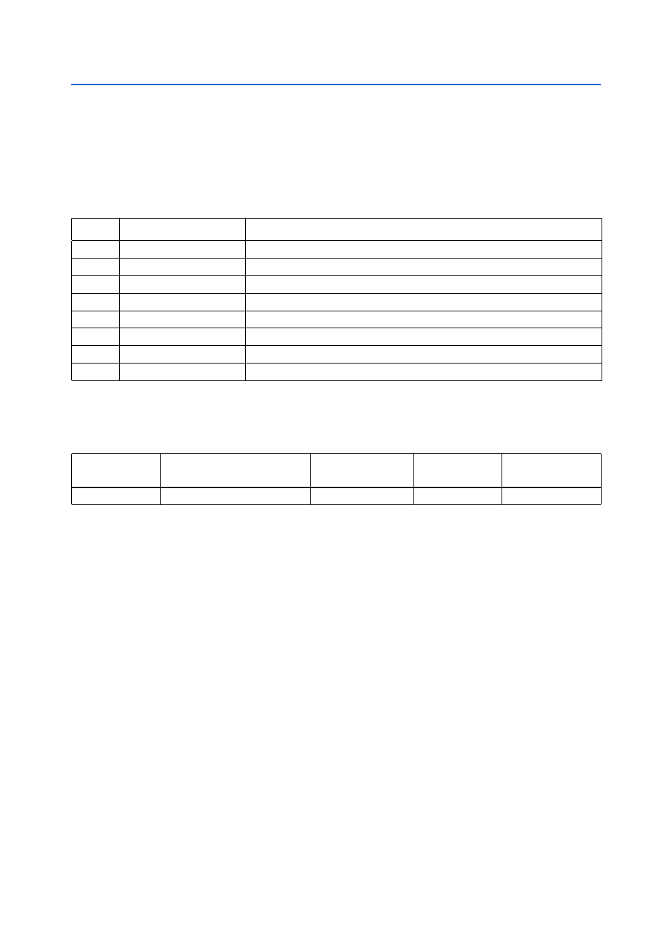
MAX II Device Control DIP Switch
Board reference SW1 is the board settings DIP switch, which controls various features
specific to the Cyclone III development board and factory default (board test system)
FPGA design: On = logic 0 and Off = logic 1.
lists the switch position, name, and description.
lists the MAX II device control DIP switch component reference and
manufacturing information.
System Reset and Configuration Switches
Board reference S6 is the system reset push button switch, RESET_CONFIGn, which is
an input to the MAX II device. It forces a reconfiguration of the FPGA from flash
memory. The location in flash memory is based on the input from the board settings
rotary switch position for the signals PGM [2:0]. The MAX II device uses the
RESET_CONFIGn
pin as its reset along with the CPU_RESETn push button.
Board reference S5 is the CPU reset push button switch, CPU_RESET, which is an
input to both the Cyclone III FPGA and the MAX II CPLD. The CPU_RESET push
button is intended to be the master reset signal for the FPGA design loaded in the
Cyclone III device, and connects to the special function pin called DEV_CLR on the
FPGA but is also a regular I/O pin. The MAX II device uses this as its reset along with
the RESET_CONFIG and FACTORY_CONFIG push buttons.
Board reference S7 is the factory push button switch (FACTORY_CONFIG), which is an
input to the MAX II device. The FACTORY_CONFIG pin forces a reconfiguration of the
FPGA with the factory default FPGA design, which is located at the base of flash
memory. See
Table 2–12. MAX II Device Control DIP Switch Position, Name, and Description
Switch
Name
Description
8
MAX3
Reserved
7
MAX2
Reserved
6
MAX1
Reserved
5
MAX0
open (1) = MAX II device PFL enabled, closed (0) = MAX II device PFL disabled
4
MAX_RESERVE1
Reserved
3
MAX_RESERVE0
Reserved
2
VOLTS_WATTS
1 = power display shows mW/mA, 0 = power display shows voltage
1
MWATTS_MAMPS
1 = power display shows mA, 0 = power display shows mW
Table 2–13. MAX II Device Control DIP Switch Component Reference and Manufacturing Information
Board Reference
Description
Manufacturer
Manufacturing
Part Number
Manufacturer
Website
SW1
8-position rocker DIP switch
Grayhill Corporation
76SB08ST
www.grayhill.com