Graphics lcd (j13) –33, Figure 2–8 – Altera Cyclone III Development Board User Manual
Page 43
Chapter 2: Board Components
2–33
General User Interfaces
© March 2009 Altera Corporation
Cyclone III 3C120 Development Board Reference Manual
1
The particular model used does not have a backlight and the LCD drive pin is not
connected.
lists the character LCD display component reference and manufacturing
information.
Graphics LCD (J13)
The board contains a 30-pin, fine-pitch connector to interface directly to a 128 × 64 dot
matrix graphics LCD display via a flex-cable that is soldered to the display itself. The
display is an Optrex part number F-51852GNFQJ-LB-AIN (blue pixels) or
F-51852GNFQJ-LB-CAN (green pixels). The pin-out of this interface connector is
compatible with a variety of displays.
1
The data signals are bused with the 14-pin LCD header.
f
For the graphics LCD data sheet and related documentation, visit
.
lists the graphics LCD pin name, description, and type. Signal name and
direction are relative to the Cyclone III FPGA.
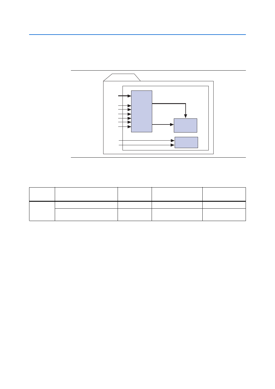
Figure 2–8. LCD Display Block Diagram
Block Diagram
16 X 2, 1/16 Duty, 1/5 Bias
E
SEC 80
COM 16
R/W
RS
Vss
VDD
Vo
DB[7:0]
LCD
Panel
LCD
Controller
LSI
and
Driver
LED Backlight
A
K
Table 2–38. Character LCD Display Component Reference and Manufacturing Information
Board
Reference
Description
Manufacturer
Manufacturing
Part Number
Manufacturer
Website
J4
2 × 7 pin, 100 mil, vertical header
Samtec
TSM-107-01-G-DV
2 × 16 character display, 5 × 8 dot
matrix
Lumex
LCM-S01602DSR/C