General user interfaces, Push button switches (s1 through s4), General user interfaces -22 – Altera Stratix II GX PCI Express Development Board User Manual
Page 31: Push button switches (s1 through s4) -22
Altera Corporation
Reference Manual
2–21
August 2006
Stratix II GX PCI Express Development Board
Board Components & Interfaces
General User
Interfaces
To allow you to fully leverage the I/O capabilities of the Stratix II GX
device for debugging, control, and monitoring purposes, the following
general user interfaces are available on the board:
■
Push buttons
■
User DIP switch
■
User LEDs
■
Board-specific DIP switch
■
Board-specific LEDs
Push Button Switches (S1 Through S4)
Board references S1 through S4 are push-button switches allowing
general user I/O interfaces to the Stratix II GX device.
The nCONFIG push button has a direct connection to the Stratix II GX
device’s nCONFIG signal that—upon pressing to drive low—forces an
erase and reprogram of the FPGA’s design. The other push buttons
connect directly to user I/O pins for user programming. Although the
RESET
push button’s purpose is programming, its special label is
intended to encourage its use as a logic reset signal for FPGA designs so
that user designs are reset in a consistent manner.
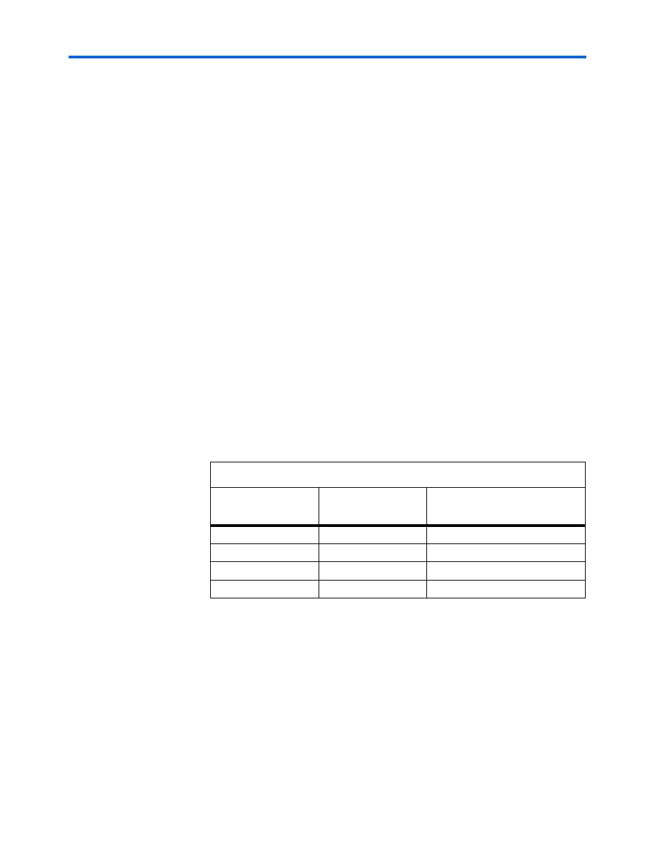
Table 2–13
lists the schematic signal names and corresponding
Stratix II GX pin numbers.
1
Board reference S1 is tied to the nCONFIG signal on the Stratix II
GX device. Pushing the S1 switch causes the FPGA to reload a
configuration from the on-board flash device. Pin AM22 is the
DEV_CLRn
pin; when enabled in the Quartus II software, it will
reset all Stratix II GX device registers. Pin AM22 can also be used
as a standard input.
Table 2–13. Push-Button Switch Signal Names and Functions
Board Reference
Schematic
Signal Name
Stratix II GX Pin Number
S1
nCONFIG
N/A
S2
USER_PB1
D37
S3
USER_PB0
E36
S4
USER_RESET
AM22