User leds (d9 through d16), Configuration dip switch (s6) – Altera Stratix II GX PCI Express Development Board User Manual
Page 33
Altera Corporation
Reference Manual
2–23
August 2006
Stratix II GX PCI Express Development Board
Board Components & Interfaces
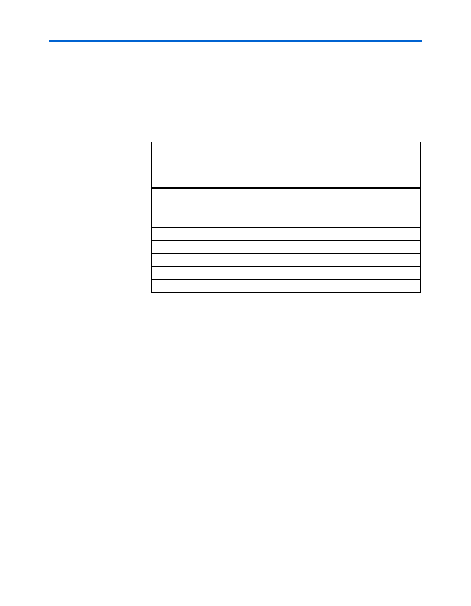
User LEDs (D9 Through D16)
The board provides eight user-defined LEDs. A logic 0 driven to an LED
turns it off; a logic 1 driven to an LED turns it on.
Table 2–15
lists the schematic signal name and the corresponding
Stratix II GX device’s pin number.
Configuration DIP Switch (S6)
The configuration DIP switch is used to set up specific board functions,
such as FPGA bootstrap settings, JTAG chain bypassing, or configuration
setup. In the open position, the selected signal is driven to logic 0. In the
closed position, the selected signal is driven to a logic 1.
Table 2–15. User-Defined LED Pin-Out
Board Reference
Schematic Signal Name
Stratix II GX Device
Pin Number
D9
USER_LED0
AR33
D10
USER_LED1
AP30
D11
USER_LED2
AT32
D12
USER_LED3
AP31
D13
USER_LED4
AU34
D14
USER_LED5
AT33
D15
USER_LED6
AN31
D16
USER_LED7
AT31