Sfp a and b interfaces (j6 and j7), Sfp a and b interfaces (j6 and j7) -34 – Altera Stratix II GX PCI Express Development Board User Manual
Page 43
Altera Corporation
Reference Manual
2–33
August 2006
Stratix II GX PCI Express Development Board
Board Components & Interfaces
SFP A and B Interfaces (J6 and J7)
Two SFP standard cages (SFP_A and SFP_B) connect to the Stratix II GX
device’s transceivers and protrude through the PCIe panel. These two
interfaces are designed per the SFP MSA specifications. Modules that
comply with the SFP MSA specifications include networking standards,
such as asynchronous transfer mode (ATM), fiber distributed data
interface (FDDI), Fiber Channel, and GigE (both copper and optical).
The SFP MSA requires signals only up to 5.0 Gb/s, but standard modules
available today are typically 2.488 Gb/s synchronous optical net
(SONET) mode or below. The board is designed to deliver electrical
transceiver signals up to 5.0 Gb/s to each SFP connector. The two
channels of transceivers dedicated from the FPGA come from the same
transceiver block as two of the channels that are routed to the HSMC-A
transceiver interface. See
“High-Speed Mezzanine Connectors A and B
.
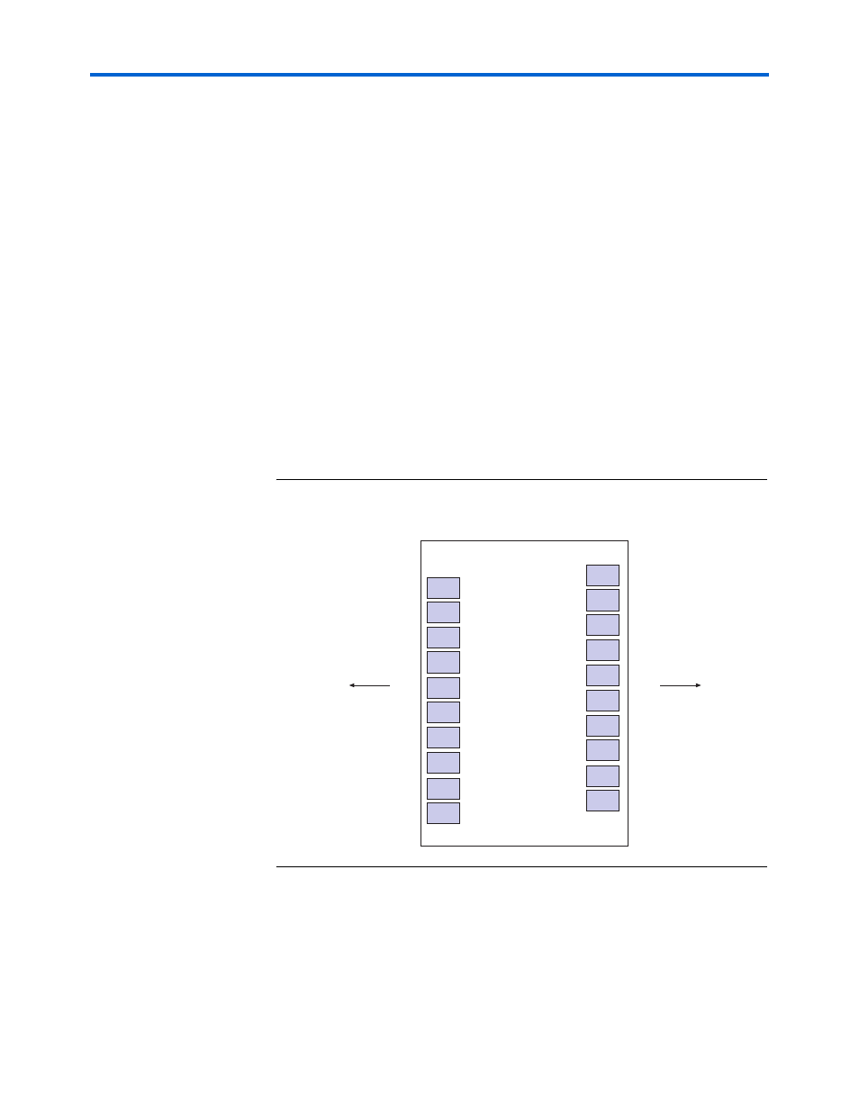
Figure 2–13
shows an SFP pin-out diagram.
Figure 2–13. SFP Pin-Out Diagram
V
ee
T
20
SFP Module
TD-
19
TD+
18
V
ee
T
17
V
cc
T
16
V
cc
R
15
V
ee
R
14
RD+
13
RD-
12
V
ee
R
11
1
20
2
TXFault
3
TXDisable
4
MOD-DEF(2)
5
Towards Bezel
Towards FPGA
MOD-DEF(1)
6
MOD-DEF(0)
7
Rate Select
8
LOS
9
V
ee
R
10
V
ee
R