Power, configuration, and traffic activity leds, Standard communication ports, Pci express edge connector interface (j9) – Altera Stratix II GX PCI Express Development Board User Manual
Page 35: Standard communication ports -27, Pci express edge connector interface (j9) -27
Altera Corporation
Reference Manual
2–25
August 2006
Stratix II GX PCI Express Development Board
Board Components & Interfaces
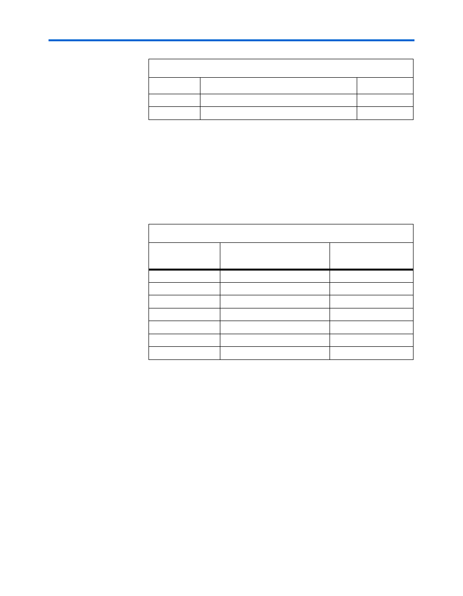
Power, Configuration, and Traffic Activity LEDs
The board provides many other special purpose LEDs. For example, a set
of display power status (PWR_ON when illuminated) LEDs as well as
FPGA configuration status LEDs (LED_ON if the FPGA is programmed).
Additionally, two other LEDs are provided to display traffic activity as
well as link status on GigE on the RJ-45 jack.
Table 2–18
shows the
transceiver interface and LED colors.
Standard
Communication
Ports
The board supports the following communication ports discussed in this
section:
■
PCIe edge connector interface
■
Gigabit Ethernet interface
■
SFP module interface
■
High-speed Mezzazine card interfaces (A and B)
■
JTAG interface
PCI Express Edge Connector Interface (J9)
The board features a x8 PCIe edge connector. The high speed PCIe signals
are directly routed to two Stratix II GX device transceivers quads. The
PCIe signals have 100 differential traces terminated on the receive-side
5
HSMC A interface (TX & RX)
Yellow
6
HSMC B interface (TX & RX)
Yellow
Table 2–18. Power, Configuration, and Traffic Activity LEDs
Number
Transceiver Interface
Indicators
LED Color
1
GigE – 10 Mb link
Green
2
GigE – 100 Mb link
Green
4
GigE – 1000 Mb link
Green
5
HSMC-A present
Green
6
HSMC-B present
Green
7
CONF_DONE
Green
8
PWR_ON
Blue
Table 2–17. FPGA Transceiver Interface LEDs (Part 2 of 2)
Number
Transceiver Interface Indicator
LED Color