Board-specific leds, Fpga transceiver channel activity leds – Altera Stratix II GX PCI Express Development Board User Manual
Page 34
2–24
Reference Manual
Altera Corporation
Stratix II GX PCI Express Development Board
August 2006
General User Interfaces
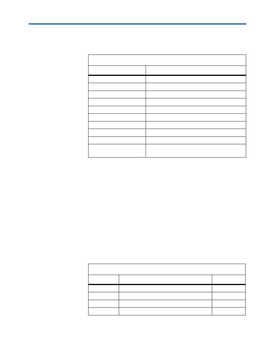
Table 2–16
shows the configuration DIP switch (S6) signal names and
descriptions.
Board-Specific LEDs
This section describes the two types of board-specific LEDs:
■
FPGA transceiver channel activity LEDs
■
Power, configuration, and traffic activity LEDs
FPGA Transceiver Channel Activity LEDs
In addition to the user-defined LEDs, the board provides a set of 12
yellow LEDs (2 per interface). These board-specified LEDs are used to
display FPGA transceiver channel activity (or traffic) on a XCVR interface
basis for both TX and RX signals.
Table 2–17
shows the channels needing TX and RX LEDs.
Table 2–16. Configuration DIP Switch (S6) Signal Names and Descriptions
Schematic Signal Name
Description
CONFIG_MODE0
Configuration mode - bit 0
CONFIG_MODE1
Configuration mode - bit 1
DIPSW_PGM0
Configuration file page select - bit 0
DIPSW_PGM1
Configuration file page select - bit 1
DIPSW_PGM2
Configuration file page select - bit 2
VCCHTX_ADJ
Transceiver power select (on = 1.5 V, off = 1.2 V)
RUnLU
Remote/local configuration mode
HSMCA_JTAG
HSMC-A JTAG bypass (close to bypass HSMC-A)
HSMCB_JTAG
HSMC-B JTAG bypass (close to bypass HSMC-B)
CLK_SEL
Local oscillator / SMA input select (on = local
oscillator)
Table 2–17. FPGA Transceiver Interface LEDs (Part 1 of 2)
Number
Transceiver Interface Indicator
LED Color
1
PCIe edge connector (L0x1, L0x4, L0x8)
Yellow
2
SFP A interface (TX & RX)
Yellow
3
SFP B interface (TX & RX)
Yellow
4
Gigabit Ethernet (TX & RX)
Yellow