3 unit rear – BINDER KT 53 User Manual
Page 18
Advertising
KT (E6) 09/2013
Page 18/135
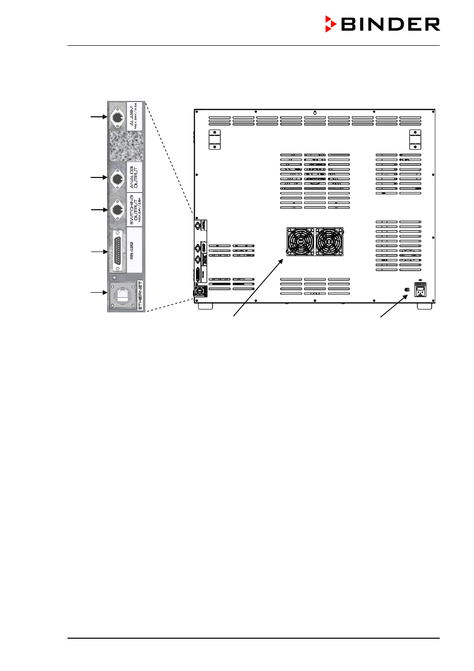
2.3 Unit rear
(1)
(3)
(4)
(5)
(6)
(7)
(8)
Figure 5: Unit rear with position of options (example KT 115)
(1)
DIN-socket for zero-voltage relay alarm outputs (option)
(2)
(not used)
(3) DIN socket for analog output 4-20 mA (option)
(4) DIN-socket for zero-voltage relay control outputs (option)
(5)
RS 422 interface for computer communication (option)
(6)
Ethernet interface for computer communication with MAC address (standard equipment, not with
optional RS 422 interface)
(7)
Peltier fan grid
(8)
Socket for IEC connector plug with power cable
Advertising