Installation, Connecting video source and output(s), Connecting control devices – Pointmaker PVI 65 User Manual
Page 31
Boeckeler Instruments, Inc.
Pointmaker PVI-65 HD/SD-SDI Broadcast Video Marker - Page 21
Section One: Getting Started
Installation
INSTALLATION
Installation of the Pointmaker PVI-65 can be divided into the following three
areas:
•
Connect Video Source and Output(s)
•
Connect Control Device(s)
•
Power Up (leaving PVI-65 to last)
Connecting Video Source and Output(s)
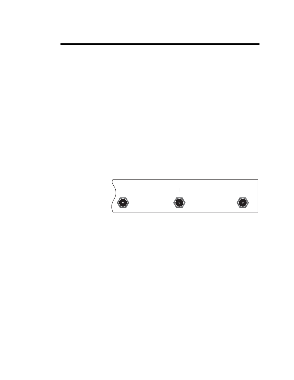
The PVI-65 supports video input/output only from SD-SDI or HD-SDI com-
patible devices. For these connections, (See “Cutaway of back panel showing
video input/output connectors.” below.).
1.
Use a BNC cable to connect your HD/SD-SDI source to the port
labeled HD/SD-SDI IN.
Figure 1-9: Cutaway of back panel showing video input/output connectors.
2.
Use a BNC cable to connect either or both video output(s) to the
port(s) labeled HD/SD-SDI OUT.
Port #1 is a Preview out, combining your video input with annotation.
Port #2 can be programmed to function as Program, Key or Preview
out. (See “Programming Video Mode“ in “Section Three: Display
Menu” on page 43)
Connecting Control Devices
The PVI-65 allows up to 10 different control devices to be attached, including
a keyboard. The following steps describe how to set up some of the most pop-
ular devices. For help in locating connectors on the Pointmaker, refer to “Cut-
away of back panel, showing power and controller connectors.” on page 22.
HD/SD-SDI OUT
2
HD/SD-SDI IN
KEY
1