Installation, Set-up an ip address, Address – Adtec digital Soloist-HD Pro (version 02.07.09) Manual User Manual
Page 21
COM1
Terminal monitor connection port for diagnostic access to unit's motherboard.
default 115200 bps
COM2
RS232 connection port for API control. default 38400 baud
ETH 10/100
(eth0)
10/100 base T ethernet interface; 2 LED indicators
Link- device networked
Busy- traffic on interface
USB 2.0
Not currently supported / Reserved for future use
SPDIF OUT
Sony/Phillips Digital Interface; compressed digital audio transport
Balanced Stereo
Audio Out
Six balanced, 600 Ohm outputs on three 5-pin mini-RST connectors
DVC PARPORT
Parallel IO Interface for Start, Stop, Status, Alarm, and general purpose
interfacing to control systems
POWER
AC Power- standard 3-pin plug (70-240 VAC 50-60 Hz)
Installation
One Soloist HD Pro server can be installed into a one-rack unit 19” rack slot. Power should be applied to
the unit and configured with a valid IP address and display target via the front panel.
Set-up an IP Address
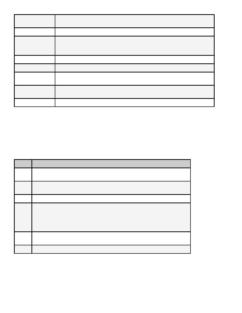
Step
Action
1
Press the <Mode> button until SYSTEM MENU is displayed on the LCD screen, then
press <Select>.
2
Press the <Down> arrow until NETWORK MENU is displayed on the LCD screen, then
press <Select>
3
Press the <Down> arrow until Ethernet IP Address item is shown on the LCD screen.
4
Enter the IP address desired for the unit using the <Select> and arrow buttons, then
press <Enter> to save.
Note: The Ethernet IP Address and IP Mask are the settings of the Ethernet port used
for control and communication. Make sure that this port is on the same network as the
control computer.
5
Press the <Down> arrow button until Ethernet IP Mask is displayed on the LCD screen,
then press <Select>.
6
Enter the IP Mask using the <Select> and arrow buttons, then press <Enter> to save.