Basler Electric IDP-1200 User Manual
Page 22
14
9437200990 Rev C
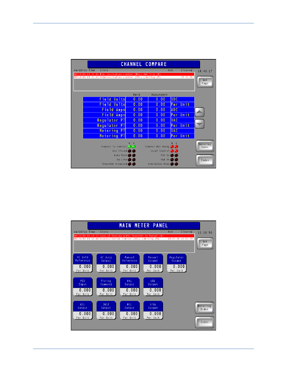
of the list, can be used to scroll up and down through the list of parameters. (A particular system may not
be equipped with all of the channels shown here.) Three columns of indicators, located in the lower
portion of the screen, show the status of various operating modes, functions, and devices for the three
channels. The Channel in Control indicators turn green when active; all other indicators turn red when
active.
Figure 12. Channel Compare Screen
Main Meter Panel, Redundant Meter Panel, and Supervisory Meter Panel Buttons
Pressing one of these Metering Index screen buttons (if so equipped) accesses the corresponding meter
panel screen which displays the digital-only version of the parameters illustrated in Figure 9. (Only the
Main Meter Panel (Figure 13) is shown here; the Redundant and Supervisory Meter Panels are similar.)
The minimum and maximum values established on the Analog Meter Configuration page determine the
metering ranges shown on this screen.
Figure 13. Main Meter Panel Screen
IDP-1200 Operation with ECS2100 and ECS/RW
IDP-1200