Alarms/faults history, Bridge status – Basler Electric IDP-1200 User Manual
Page 28
20
9437200990 Rev C
Alarms/Faults History
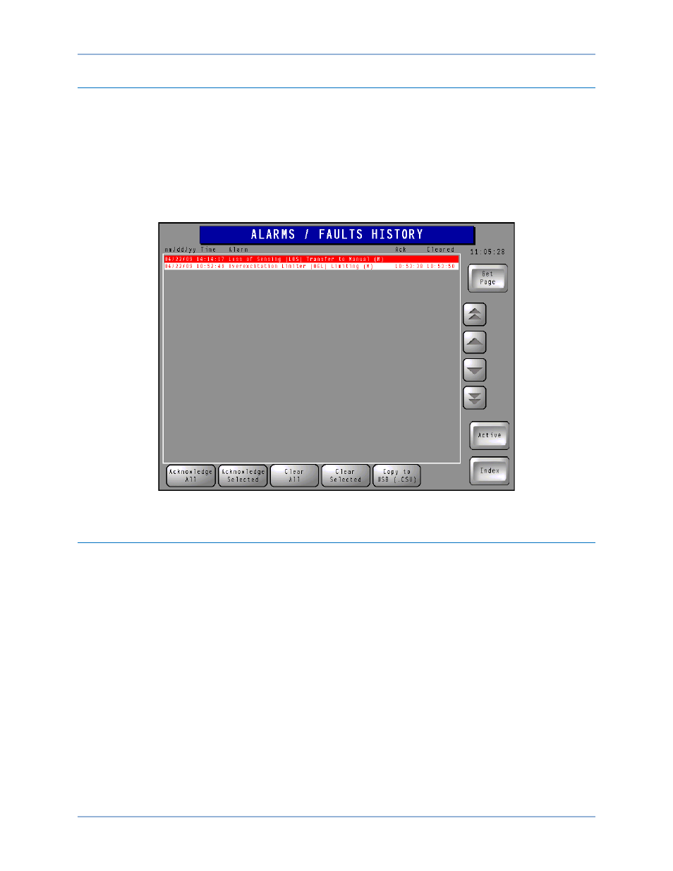
This screen (Figure 21) lists all active, acknowledged, and cleared alarms. Active alarms are displayed as
white text on a red background. Alarms that have been acknowledged (but not cleared) are displayed as
yellow text on a black background. Cleared alarms are displayed as red text on a white background.
Scrolling buttons along the right side of the list enable the user to navigate through the list of alarms.
Individual alarms can be acknowledged or cleared by selecting the alarm and then pressing the
Acknowledge Selected or Clear Selected button. All alarms in the list can be simultaneously
acknowledged or cleared by pressing the Acknowledge All or Clear All button. A Copy to USB button
provides the ability to export the plot data to the IDP-1200’s USB port in a comma-separated-values file
format. The History button provides access to the Active Alarms/Faults screen.
Figure 21. Alarms/Faults History Screen
Bridge Status
The Bridge Status screen (Figure 22) displays alarm conditions associated with the excitation system
power converters. This screen indicates the status of up to two power converters; a system with more
than two power converters will have more than one Bridge Status screen.
Alarm indications are provided for open input fuses, open or non-conducting SCRs, open or shorted
RTDs, and cooling failures.
A Reset FCIM Alarms button can be used to reset any alarms associated with the Field Control Interface
Module.
The Return Bridge From Maint button must be pressed when an out-of-service power converter is ready
to be returned to service.
IDP-1200 Operation with ECS2100 and ECS/RW
IDP-1200