Mstp configuration example, Network requirements, Configuration procedure – H3C Technologies H3C WX3000E Series Wireless Switches User Manual
Page 96
86
Task Command
Remarks
Display the MST region configuration
information that has taken effect.
display stp region-configuration [ |
{ begin | exclude | include }
regular-expression ]
Available in any
view.
Display the root bridge information of all
MSTIs.
display stp root [ | { begin | exclude |
include } regular-expression ]
Available in any
view.
Clear the spanning tree statistics.
reset stp [ interface interface-list ]
Available in user
view.
MSTP configuration example
Network requirements
As shown in
:
•
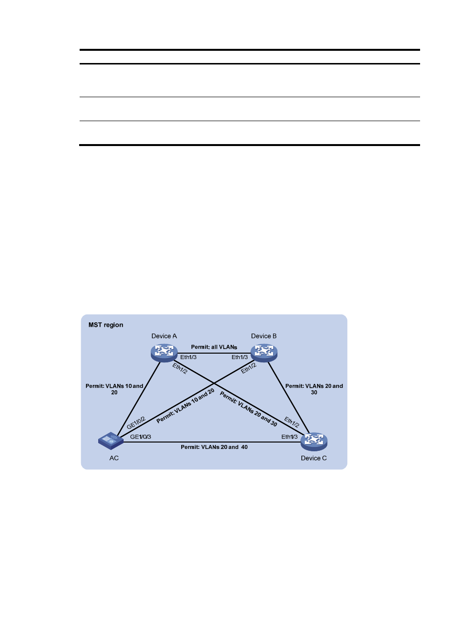
All devices on the network are in the same MST region. Configure MSTP so that packets of different
VLANs are forwarded along different spanning trees: Packets of VLAN 10 are forwarded along
MSTI 1, those of VLAN 30 are forwarded along MSTI 3, those of VLAN 40 are forwarded along
MSTI 4, and those of VLAN 20 are forwarded along MSTI 0.
•
Configure the root bridges of MSTI 1 and MSTI 3 as Device A and Device B respectively, and the
root bridge of MSTI 4 as the AC.
Figure 23 Network diagram
Configuration procedure
1.
Configure VLANs and VLAN member ports: (Details not shown.)
{
Create VLAN 10, VLAN 20, and VLAN 30 on Device A and Device B respectively.
{
Create VLAN 10, VLAN 20, and VLAN 40 on the AC.
{
Create VLAN 20, VLAN 30, and VLAN 40 on Device C.
{
Configure the ports on these devices as trunk ports and assign them to related VLANs.
G
E
1
/0
/1
E
th
1
/1
E
th
1
/1
E
th
1
/1